1. Introduction
This manual provides detailed instructions for the JESSINIE ZK-MG PWM Motor Speed Controller. This device is designed to precisely control the speed of DC motors using Pulse Width Modulation (PWM), offering features such as soft start, adjustable duty cycle, and frequency settings. Its digital display and encoder knob ensure accurate and convenient operation for various applications.

Figure 1: ZK-MG PWM Motor Speed Controller
2. Safety Information
- Ensure the power supply voltage is within the specified range (DC 5V-30V).
- Do not exceed the maximum current rating of 5A.
- Always disconnect power before making any wiring connections.
- Avoid short circuits between terminals.
- Keep the device away from moisture, dust, and extreme temperatures.
- This device is intended for DC motor speed control; do not use it for AC applications.
3. Product Overview
3.1 Components

Figure 2: Key Components and Controls
- Digital Tube Display: Shows the current duty cycle percentage, frequency, and parameter settings.
- Rotary Encoder Knob: Used to adjust motor speed (duty cycle) and navigate settings. Turn left to decrease, right to increase. Short press to start/stop the motor. Long press to enter setting mode.
- ON/OFF Switch: Controls the power to the module.
- Motor Start-Stop Indicator: Light indicates motor status (on/off).
4. Setup
4.1 Wiring Connections
Refer to the diagram below for proper wiring. Ensure correct polarity for both power input and motor output.

Figure 3: Wiring Diagram
- V+ (Power Input Positive): Connect to the positive terminal of your DC power supply (5V-30V).
- V- (Power Input Negative): Connect to the negative terminal of your DC power supply.
- OUT+ (Motor Output Positive): Connect to the positive terminal of your DC motor.
- OUT- (Motor Output Negative): Connect to the negative terminal of your DC motor.
- STOP (External Switch): The switch signal or 3.3V level signal can be connected here to control the motor start and stop externally.
5. Operating Instructions
5.1 Basic Operation
Once wired and powered on, the digital display will show the current duty cycle. The ZK-MG controller features a soft start function, gradually increasing current to protect the motor upon startup.
- Adjusting Speed: Rotate the encoder knob. Turning it clockwise increases the duty cycle (motor speed), and counter-clockwise decreases it. The display shows the percentage.
- Start/Stop Motor: Short press the encoder knob to toggle the motor between running and stopped states.
5.2 Parameter Settings
The controller allows setting the lower limit of the duty cycle, the upper limit of the duty cycle, and the operating frequency.

Figure 4: Adjusting Parameters
- Enter Setting Mode: Long press the encoder knob for approximately 3 seconds until the display changes to show a setting parameter.
- Navigate Settings: Short press the encoder knob to cycle through the parameters: L (Lower Duty Cycle Limit) → H (Upper Duty Cycle Limit) → F (Frequency).
- Adjust Value: When the desired parameter is displayed, rotate the encoder knob to adjust its value.
- Save and Exit: Long press the encoder knob again to save the settings and exit the setting mode. The display will return to the normal operating mode.
6. Maintenance
- Keep the device clean and free from dust. Use a soft, dry cloth for cleaning.
- Ensure proper ventilation around the module to prevent overheating.
- Regularly check wiring connections for looseness or damage.
- Do not attempt to disassemble the unit beyond what is necessary for wiring.
7. Troubleshooting
| Problem | Possible Cause | Solution |
|---|---|---|
| Motor does not run | No power; incorrect wiring; motor stopped via knob/external switch; faulty motor. | Check power supply; verify wiring polarity; short press knob to start; test motor separately. |
| Display is off | No power; faulty unit. | Check power supply and connections; ensure ON/OFF switch is on. |
| Motor speed is inconsistent | Unstable power supply; motor overload; incorrect frequency setting. | Ensure stable power; reduce motor load; adjust frequency setting. |
| Cannot enter setting mode | Knob not pressed long enough. | Long press the encoder knob for at least 3 seconds. |
8. Specifications
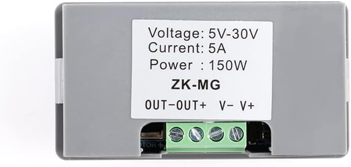
Figure 5: Back Label with Power Specifications
| Feature | Specification |
|---|---|
| Model | ZK-MG |
| Operating Voltage | DC 5V ~ 30V |
| Operating Frequency | 1KHz ~ 99KHz (Adjustable) |
| Duty Cycle Range | 0-100% |
| Maximum Current | 5A |
| Maximum Power | 150W |
| Display Type | LED Digital Display |
| Control Method | Rotary Encoder Knob |
| Dimensions (L x W x H) | 3.11 x 1.69 x 1.02 inches (79 x 43 x 26 mm) |
| Item Weight | 1.44 ounces |
| Material | Copper (internal components) |
| Color | Gray |

Figure 6: Product Dimensions
9. Warranty and Support
For warranty information and technical support, please refer to the product packaging or contact JESSINIE customer service through the retailer where the product was purchased. Please have your product model number (ZK-MG) and purchase details ready when contacting support.