1. Introduction
The Goalake POE104D V6 is a 5-port 100Mbps PoE+ switch designed for efficient and reliable network connectivity, particularly for Power over Ethernet (PoE) devices. It features four 10/100Mbps PoE ports and one 10/100Mbps uplink port, providing a total PoE power budget of 52W, with up to 30W per port. This switch supports the 802.3af/at standard and includes advanced AI functions such as 250-meter extended transmission, AI Watchdog, and AI PD detection. Its robust design incorporates 4KV lightning protection and short-circuit safeguards, making it suitable for various applications including IP surveillance and wireless access points.

Image 1.1: Overview of the Goalake 5-Port PoE Switch, highlighting its stability, reliability, and plug-and-play functionality.
2. Package Contents
Please verify that all items are present and in good condition upon opening the package:
- Goalake 5-Port PoE+ Switch (Model: POE104D V6)
- AC Power Cable
- Screws (for mounting options)
- User Manual
3. Product Overview
The Goalake POE104D V6 switch features a compact metal housing with clearly labeled ports and indicators on the front panel.
Front Panel Layout

Image 3.1: Front panel of the Goalake POE104D V6 switch, showing PoE ports, uplink port, and LED indicators.
- PoE Ports (1-4): Four 10/100Mbps RJ45 ports that provide both data and power to connected PoE-compatible devices.
- Uplink Port (LAN): One 10/100Mbps RJ45 port for connecting to a router, NVR, or main network.
- LED Indicators:
- PWR (Power): Indicates the power status of the switch.
- AI: Indicates the status of the AI functions (e.g., AI Extend mode).
- Port LEDs: Indicate link/activity status for each port.
- AI Switch (OFF/ON): Toggles the AI functions.
- 4KV: Indicates 4KV lightning protection feature.
Integrated Power Supply
The switch features an integrated power supply, simplifying installation by eliminating the need for an external power adapter brick.

Image 3.2: Diagram illustrating the built-in power supply and port functions of the 5-Port PoE+ Switch.
4. Setup Instructions
The Goalake POE104D V6 switch is designed for plug-and-play operation, requiring no complex configuration.
Basic Connection Steps:
- Connect to Power: Plug the AC power cable into the switch's power inlet and then into a standard electrical outlet. The PWR LED indicator on the front panel should illuminate.
- Connect to Network (Uplink): Connect an Ethernet cable from your router, NVR, or main network device to the 'LAN' (Uplink) port on the switch.
- Connect PoE Devices: Connect your PoE-compatible devices (e.g., IP cameras, wireless access points, VoIP phones) to any of the PoE Ports (1-4) using Ethernet cables. The switch will automatically detect and power these devices.
- Connect Non-PoE Devices (Optional): If connecting non-PoE devices that require power, use an active PoE splitter. Connect the splitter to a PoE port on the switch, and then connect the non-PoE device to the splitter. For non-PoE devices that do not require power from the switch (e.g., a desktop computer), they can be connected to any port, but will require their own power source.
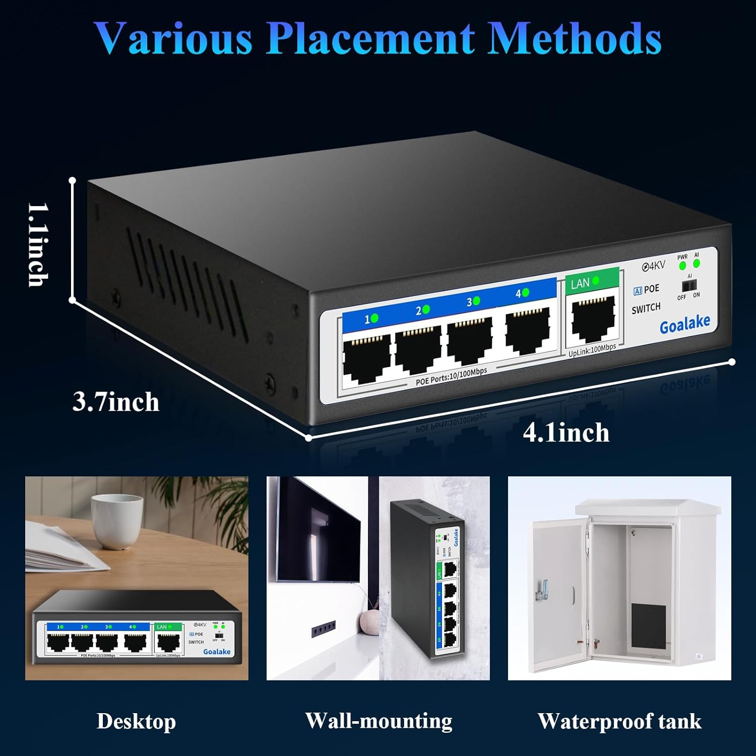
Image 4.1: Diagram illustrating the simple plug-and-play installation process for the switch.

Image 4.2: Visual guide for connecting power and various devices to the switch.
5. Operating Instructions
The Goalake POE104D V6 operates as an unmanaged switch, meaning it requires no software configuration. Once connected, it automatically handles data transmission and power delivery.
PoE (Power over Ethernet) Functionality
The switch is compliant with IEEE 802.3af/at standards, ensuring compatibility with a wide range of active PoE devices. It intelligently detects if a connected device requires power and supplies it accordingly.
- Active PoE Devices: Connect directly to PoE Ports 1-4. The switch will provide both data and power.
- Passive PoE Devices or Non-PoE Devices: When connecting a passive PoE device or a non-PoE device, the switch will only transmit data. These devices must be powered separately or used with an active PoE splitter to receive power from the switch.
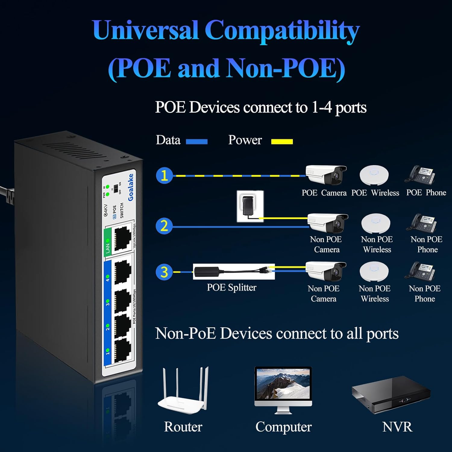
Image 5.1: Diagram showing how to connect various PoE and non-PoE devices to the switch, including the use of a PoE splitter.
6. AI Functions
The Goalake POE104D V6 switch incorporates several AI-powered features to enhance network performance and reliability. These functions can be enabled or disabled using the AI switch on the front panel.

Image 6.1: Close-up of the AI switch (OFF/ON) on the front panel.
AI Extension (250 Meters)
When the AI switch is turned ON, the device enters AI mode. In this mode, the PoE ports can extend the maximum power and data transmission distance from 100 meters to up to 250 meters. This is particularly useful for deploying devices like IP cameras in locations without nearby power outlets, extending network reach over longer Ethernet cable runs. Note that in AI Extend mode, the data rate for extended ports may be reduced to 10Mbps.
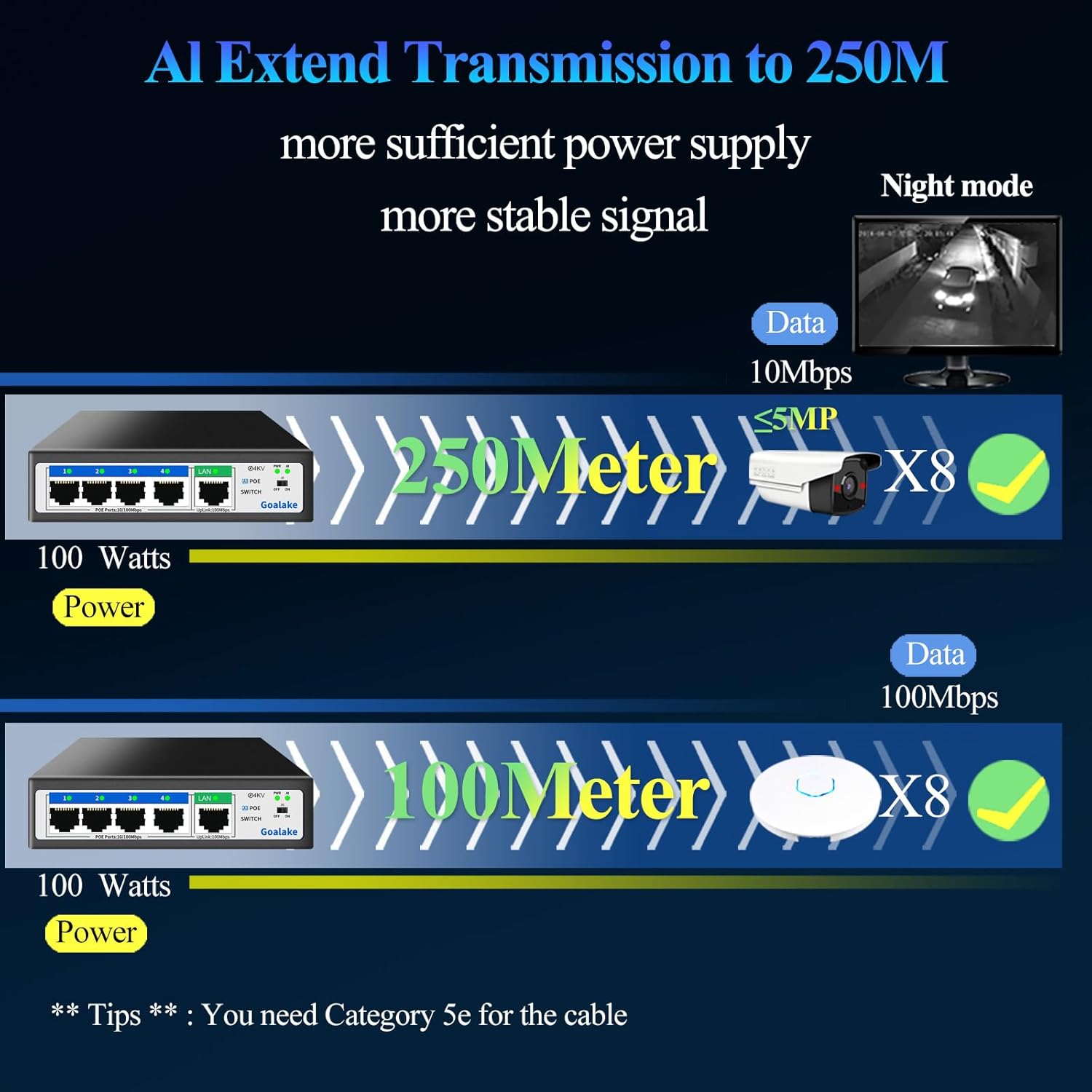
Image 6.2: Diagram illustrating the AI Extend feature, allowing data and power transmission up to 250 meters.
AI Watchdog Function
With the AI switch ON, the AI Watchdog function monitors the data and power transmission between the PoE port and the connected terminal device. If an abnormal connection or transmission issue is detected, the corresponding PoE port will automatically detect the problem and restart the connection, restoring normal operation without manual intervention.
AI PD Detection
The AI PD Detection feature allows the PoE port to intelligently determine if a connected device requires power. If a non-PoE device is connected that does not need power, the switch will not supply power to that device, preventing potential damage and ensuring safe operation.
7. Protection Features
The Goalake POE104D V6 switch is equipped with multiple protection mechanisms to ensure stable and safe operation of your network and connected devices.
4KV Lightning Protection
The switch features professional 4KV lightning protection on its ports and power supply. This two-level protection effectively limits lightning surges from the cable, providing a safety barrier for the entire network surveillance system.

Image 7.1: Illustration of the 4KV lightning protection feature.
Network Cable Short-Circuit Protection
The Goalake PoE switch is designed with a robust short-circuit protection mechanism for network ports. This feature safeguards against faults caused by short circuits in the network cable, preventing damage to both the switch and connected devices. It also includes overcurrent and overvoltage protection.
8. Maintenance
To ensure optimal performance and longevity of your Goalake POE104D V6 switch, consider the following maintenance guidelines:
- Fanless Design: The switch features a fanless design, which means it operates silently and reduces the accumulation of dust internally. No fan cleaning is required.
- Operating Environment: Ensure the switch is operated within its specified temperature range (0°C to 60°C) and in a well-ventilated area to prevent overheating.
- Cleaning: Use a soft, dry cloth to clean the exterior of the switch. Avoid using liquid cleaners or aerosols.
- Placement: The switch can be placed on a desktop, wall-mounted, or installed in a waterproof enclosure for outdoor use. Ensure stable placement and proper cable management.

Image 8.1: Illustration of the fanless design, ensuring silent operation.

Image 8.2: Diagram showing the wide operating temperature range of the switch.

Image 8.3: Examples of different placement methods: desktop, wall-mounting, and within a waterproof tank.
9. Troubleshooting
If you encounter issues with your Goalake POE104D V6 switch, refer to the following common troubleshooting steps:
- No Power:
- Ensure the AC power cable is securely connected to both the switch and a working power outlet.
- Check if the power outlet is functional by plugging in another device.
- Verify the PWR LED on the switch is illuminated.
- No Data Connection:
- Check that Ethernet cables are securely connected to both the switch ports and the connected devices.
- Verify the link/activity LEDs for the respective ports are blinking or solid.
- Ensure the uplink port is correctly connected to your router or main network.
- Test with different Ethernet cables to rule out cable faults.
- PoE Device Not Receiving Power:
- Confirm the connected device is PoE-compatible (IEEE 802.3af/at standard).
- Ensure the total power consumption of all connected PoE devices does not exceed the switch's 52W budget.
- If using AI Extend mode, ensure the device is compatible with the reduced 10Mbps speed.
- If the AI Watchdog function is enabled, it may automatically restart the port if an issue is detected.
- For passive PoE devices or non-PoE devices, ensure an active PoE splitter is used if power is required from the switch.
- AI Functions Not Working:
- Ensure the AI switch on the front panel is set to 'ON'.
- Check the AI LED indicator for status.
10. Specifications
| Feature | Specification |
|---|---|
| Model Number | POE104D V6 |
| Brand | Goalake |
| Number of Ports | 5 (4 PoE Ports + 1 Uplink Port) |
| Data Transfer Rate | 100 Mbps (per port) |
| Interface Type | RJ45 |
| PoE Standard | IEEE 802.3af/at |
| Max Power per PoE Port | 30 Watt |
| Total PoE Power Budget | 52 Watt |
| AI Extension Distance | Up to 250 meters (at 10Mbps) |
| Protection Features | 4KV Lightning Protection, Short-Circuit Protection, Overcurrent, Overvoltage |
| Housing Material | Metal |
| Color | Black |
| Product Dimensions (L x W x H) | 12.5 x 11.5 x 3.4 cm |
| Operating Temperature | 0°C to 60°C |
| Compatible Devices | Desktop, Camera, Wireless Access Points, VoIP Phones |
| Manufacturer | SSC |
11. Warranty and Support
Goalake provides a one-year after-sales service for this product. Within one year from the order date, the service includes product replacement for unexplained failures, rather than repair. For support or warranty claims, please contact your retailer or Goalake customer service.