Teyleten Robot Type-C Pro Micro ATmega32U4 5V 16MHz Module
Teyleten Robot Type-C Pro Micro ATmega32U4 Module User Manual
Model: Type-C Pro Micro ATmega32U4 5V 16MHz Module
1. Introduction
This user manual provides comprehensive instructions for the Teyleten Robot Type-C Pro Micro ATmega32U4 5V 16MHz Module. This compact development board is designed for various embedded projects, offering robust performance and versatile connectivity. Please read this manual thoroughly before use to ensure proper setup and operation.
2. Key Features
- Microcontroller: ATmega32U4 running at 5V/16MHz.
- USB Interface: On-board Type-C USB connector for programming and communication.
- Analog Inputs: 4 x 10-bit Analog-to-Digital Converter (ADC) pins.
- Digital I/O: 12 x Digital Input/Output pins, 5 of which are Pulse Width Modulation (PWM) capable.
- Serial Communication: Hardware Serial Connections (Rx and Tx).
- IDE Support: Supported under Arduino IDE v1.0.1 and later.
- Power Protection: Includes PTC fuse and diode protection for the power circuit.
- Compact Design: Small form factor suitable for integration into various projects.
3. Package Contents
Verify that all items are present in your package:
- 3 x Teyleten Robot Type-C Pro Micro ATmega32U4 Modules
- Pin headers (if included in packaging)

Image 3.1: Package contents showing three Pro Micro modules.
4. Technical Specifications
| Microcontroller | ATmega32U4 |
| Operating Voltage | 5V |
| Clock Speed | 16 MHz |
| Digital I/O Pins | 12 (5 PWM capable) |
| ADC Pins | 4 (10-bit) |
| USB Connector | Type-C |
| Recommended Power Supply | 6-7V (max 9V) to RAW pin |
| Operating Systems Supported | Linux, Windows, macOS |
5. Pinout Diagram
Understanding the pinout is crucial for connecting the module to other components. Refer to the diagram below for detailed pin assignments.

Image 5.1: Top view of the Pro Micro module with pin labels. This image displays the ATmega32U4 chip, crystal oscillator, and various labeled pins including A0-A3, D0-D10, RAW, GND, VCC, RST, TXO, RXI.

Image 5.2: Alternative top view of the Pro Micro module, highlighting the Type-C USB port and surrounding components. This view provides a clearer perspective of the USB connector and its integration with the board.

Image 5.3: Detailed close-up of the Type-C USB port, emphasizing its robust design and connection interface. This image confirms the Type-C standard for modern connectivity.
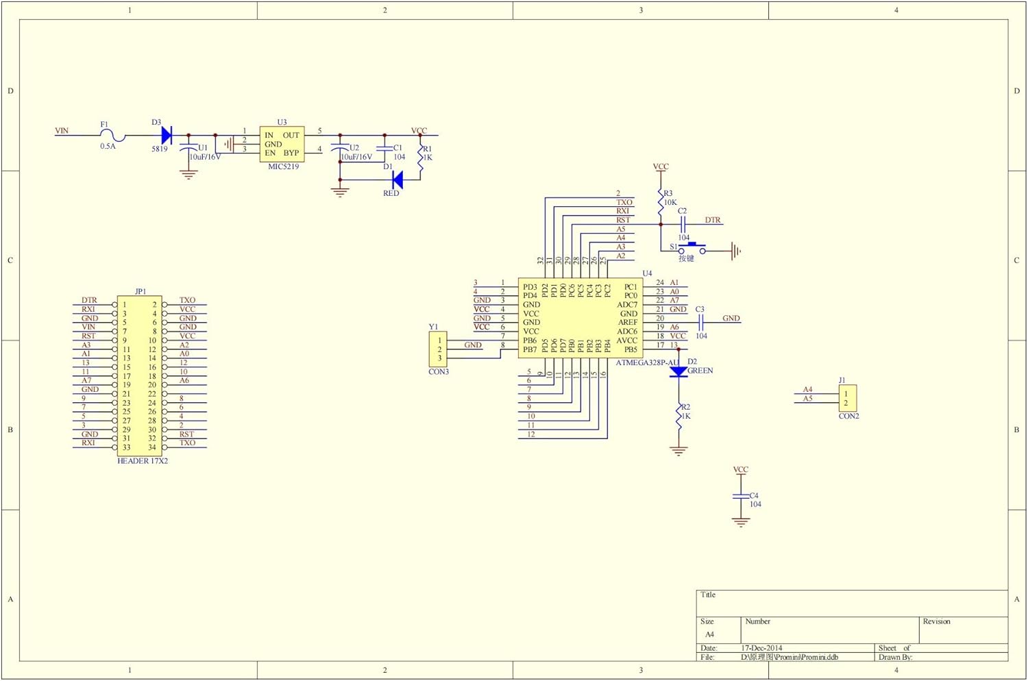
Image 5.4: Schematic diagram of the Pro Micro module, illustrating the internal circuit connections and component layout. This diagram is useful for advanced users and troubleshooting.
6. Setup Instructions
6.1. Software Installation (Arduino IDE)
- Download and install the latest version of the Arduino IDE from the official Arduino website (www.arduino.cc/en/software).
- Open the Arduino IDE.
- Go to Tools > Board > Board Manager....
- Search for "SparkFun AVR Boards" and install the package. This package includes support for the Pro Micro.
- After installation, go to Tools > Board and select "SparkFun Pro Micro". Ensure "ATmega32U4 (5V, 16MHz)" is selected as the processor.
6.2. Connecting the Module
- Connect the Teyleten Robot Pro Micro module to your computer using a Type-C USB cable.
- The module should be recognized by your operating system, and a new COM port (Windows) or /dev/ttyACM* (Linux/macOS) should appear.
- In the Arduino IDE, go to Tools > Port and select the newly appeared serial port.

Image 6.1: Bottom view of the Pro Micro module, indicating the 5V and 3.3V power selection jumpers. Ensure correct power configuration for your project.
Power Supply: The board can be powered via the USB Type-C port. If supplying unregulated power, connect it to the "RAW" pin. The recommended unregulated power supply is 6-7V, not exceeding 9V. Do not connect unregulated power to the VCC pin.
7. Operating Instructions
7.1. Uploading a Sketch
- Open an example sketch in the Arduino IDE (e.g., File > Examples > 01.Basics > Blink).
- Ensure the correct board (SparkFun Pro Micro, ATmega32U4 5V/16MHz) and port are selected under the Tools menu.
- Click the "Upload" button (right arrow icon) in the Arduino IDE. The IDE will compile the sketch and upload it to the Pro Micro module.
- During upload, the RX and TX LEDs on the board may flash. Upon successful upload, the sketch will begin running.
7.2. Using Digital I/O and Analog Pins
- Digital I/O: Use
pinMode(),digitalWrite(), anddigitalRead()functions to control digital pins. - PWM: Pins D3, D5, D6, D9, D10 are PWM capable. Use
analogWrite()for PWM output. - Analog Input: Pins A0-A3 can be used for analog input. Use
analogRead()to read analog values.
8. Maintenance and Care
- Keep the module in a dry environment to prevent moisture damage.
- Avoid exposing the board to extreme temperatures or direct sunlight.
- Handle the board by its edges to prevent electrostatic discharge (ESD) damage to components.
- Ensure proper power supply connections to avoid overvoltage or reverse polarity damage.
- Clean the board gently with a soft, dry brush if dust accumulates. Do not use liquids.
9. Troubleshooting
- Issue: Module not recognized by computer / No power LED.
Solution 1: Ensure the USB Type-C cable is fully inserted and functional. Try a different cable or USB port.
Solution 2: Verify that the correct drivers are installed. For Arduino IDE, ensure the "SparkFun AVR Boards" package is installed.
Solution 3: If the board was previously programmed, it might be in a state where it doesn't immediately enumerate as a serial device. Try pressing the reset button twice quickly to enter the bootloader mode, then attempt to upload a sketch.
- Issue: Sketch upload fails.
Solution 1: Check if the correct board ("SparkFun Pro Micro") and port are selected in the Arduino IDE's Tools menu.
Solution 2: Ensure no other applications are using the serial port.
Solution 3: If you encounter "programmer not responding" errors, try pressing the reset button on the Pro Micro just before the upload process starts (when the IDE displays "Uploading...").
- Issue: External components not working as expected.
Solution 1: Double-check your wiring against the pinout diagram (Section 5).
Solution 2: Verify that your external components are receiving the correct voltage and current. Ensure the Pro Micro's power output is sufficient.
Solution 3: Review your code for logical errors or incorrect pin assignments.
10. Warranty and Support
Teyleten Robot products are designed for reliability and performance. For warranty information or technical support, please contact Teyleten Robot customer service through the retailer where the product was purchased or visit the official Teyleten Robot website.
Please retain your proof of purchase for warranty claims.
Ask a question about this manual
Ask about setup, troubleshooting, compatibility, parts, safety, or missing instructions. Manuals+ will review the question and use this page’s manual context to help answer it.