1. Introduction
Thank you for choosing the Perlegear PGLCM1 Ceiling TV Mount. This manual provides detailed instructions for safe and proper installation, operation, and maintenance of your new TV mount. Please read this manual thoroughly before installation to ensure correct assembly and to prevent any potential damage or injury. Keep this manual for future reference.

Image: Overview of the Perlegear PGLCM1 Ceiling TV Mount, showing its main components and how it appears when installed with a television.
2. Important Safety Information
WARNING: Failure to read and follow all instructions, warnings, and cautions in this manual may result in serious personal injury, property damage, or voiding of your warranty.
- Do not begin installation until you have read and understood all instructions and warnings contained in this installation sheet. If you have any questions regarding any of the instructions or warnings, please contact your local distributor for assistance.
- This mounting bracket is designed to be installed only by qualified installation personnel.
- The mounting surface must be capable of supporting five times the weight of the TV and the mount combined.
- Do not use this product for any purpose not explicitly specified by the manufacturer.
- The manufacturer is not responsible for damage or injury caused by incorrect assembly or use.
- Always use appropriate safety equipment and proper tools for installation.
- Ensure all screws are tightened securely but do not overtighten. Overtightening can damage the screws and components.
- This product contains small items that could be a choking hazard if swallowed. Keep these items away from children.
3. Package Contents
Please verify that all parts are present and undamaged before beginning installation. If any parts are missing or damaged, do not attempt to install. Contact customer service for replacement parts.
| Part | Description | Quantity |
|---|---|---|
| Ceiling Plate | Mounting plate for ceiling attachment | 1 |
| Telescopic Pole | Adjustable height pole | 1 |
| TV Plate | Plate for attaching TV brackets | 1 |
| TV Brackets | Vertical bars that attach to the TV | 2 |
| Hardware Kit | Assorted screws, washers, spacers, and anchors | 1 set |
| Bubble Level | For accurate leveling during installation | 1 |
| Cable Ties | For cable management | 5 |
4. Product Specifications
- Model: PGLCM1
- Screen Size Compatibility: 37 - 75 inches
- Weight Capacity: Up to 99 lbs (45 kg)
- VESA Compatibility: 200x100mm to 600x400mm (Horizontal x Vertical)
- Height Adjustment: 28.23 inches to 40.04 inches (from ceiling to TV plate)
- Tilt Angle: +5° to -15°
- Swivel Angle: 360°
- Level Adjustment: +/-3°
- Ceiling Type: Flat or Sloped (up to ±60°)
- Material: Alloy Steel
- Color: Black

Image: Visual representation of the mount's wide compatibility, including supported TV sizes (37"-75"), maximum weight (99 lbs), and VESA mounting patterns (Min 200x100mm, Max 600x400mm).
5. Setup & Installation
5.1 Pre-Installation Checks
- Verify TV Compatibility:
- Check your TV's weight. It must be less than 99 lbs (45 kg).
- Measure your TV's VESA mounting pattern (horizontal x vertical distance between screw holes). It must be between 200x100mm and 600x400mm.
- Ensure your TV size is between 37 and 75 inches.
- Identify Ceiling Type: This mount is suitable for wood joist ceilings, concrete ceilings, and brick ceilings.

Image: Important checks before purchase, including VESA pattern, TV weight and size, and compatible ceiling types (ceiling joist, concrete ceiling, brick ceiling).
- Gather Tools: You will need a drill, stud finder (for wood joists), level, pencil, and a Phillips head screwdriver.
5.2 Mounting the Ceiling Plate
- Locate the center of your desired mounting area on the ceiling. For wood joists, use a stud finder to locate the center of a joist. For concrete/brick, ensure the area is solid.
- Position the ceiling plate (A) against the ceiling and mark the pilot hole locations.
- Drill pilot holes. For wood joists, drill 5.5mm (7/32") diameter holes to a depth of 60mm (2.36"). For concrete/brick, drill 10mm (3/8") diameter holes to a depth of 60mm (2.36") and insert concrete anchors (WA).
- Attach the ceiling plate (A) to the ceiling using the lag bolts (WB) and washers (WC). Tighten securely.
- If mounting on a sloped ceiling, adjust the ceiling plate's angle using the pivot mechanism. The mount supports slopes up to ±60°.

Image: The ceiling mount's ability to be installed on both flat and sloped ceilings, demonstrating its ±60° angle adjustment.
5.3 Assembling the Pole and TV Plate
- Attach the telescopic pole (B) to the ceiling plate (A). Secure with the provided screws.
- Attach the TV plate (C) to the bottom of the telescopic pole (B). Secure with the provided screws.
5.4 Attaching TV Brackets to TV
- Carefully place your TV face down on a soft, clean surface.
- Identify the correct diameter and length of screws (MA, MB, MC, MD, ME, MF) for your TV's VESA holes. Use washers (MG, MH) and spacers (MI, MJ) if needed to ensure a flush fit and prevent damage to the TV.
- Attach the TV brackets (D) to the back of your TV using the selected screws, washers, and spacers. Ensure the brackets are centered and level.
5.5 Mounting TV to Ceiling Mount
- With assistance, carefully lift the TV with the attached brackets and hook the brackets onto the TV plate (C).
- Secure the TV to the TV plate by tightening the safety screws located at the bottom of the TV brackets.
6. Operating Instructions
6.1 Height Adjustment
The telescopic pole allows for 6 height settings, extending from 28.23 inches to 40.04 inches (from the ceiling to the TV plate). To adjust the height, loosen the locking mechanism on the pole, extend or retract to the desired height, and then securely tighten the locking mechanism.

Image: The adjustable height feature of the mount, demonstrating the range from 28.23 inches to 40.04 inches.
6.2 Tilt Adjustment
The mount allows for a tilt range of +5° (upwards) to -15° (downwards) to reduce glare and optimize viewing angles. Loosen the tilt adjustment knobs on the TV plate, adjust the TV to the desired angle, and then securely tighten the knobs.
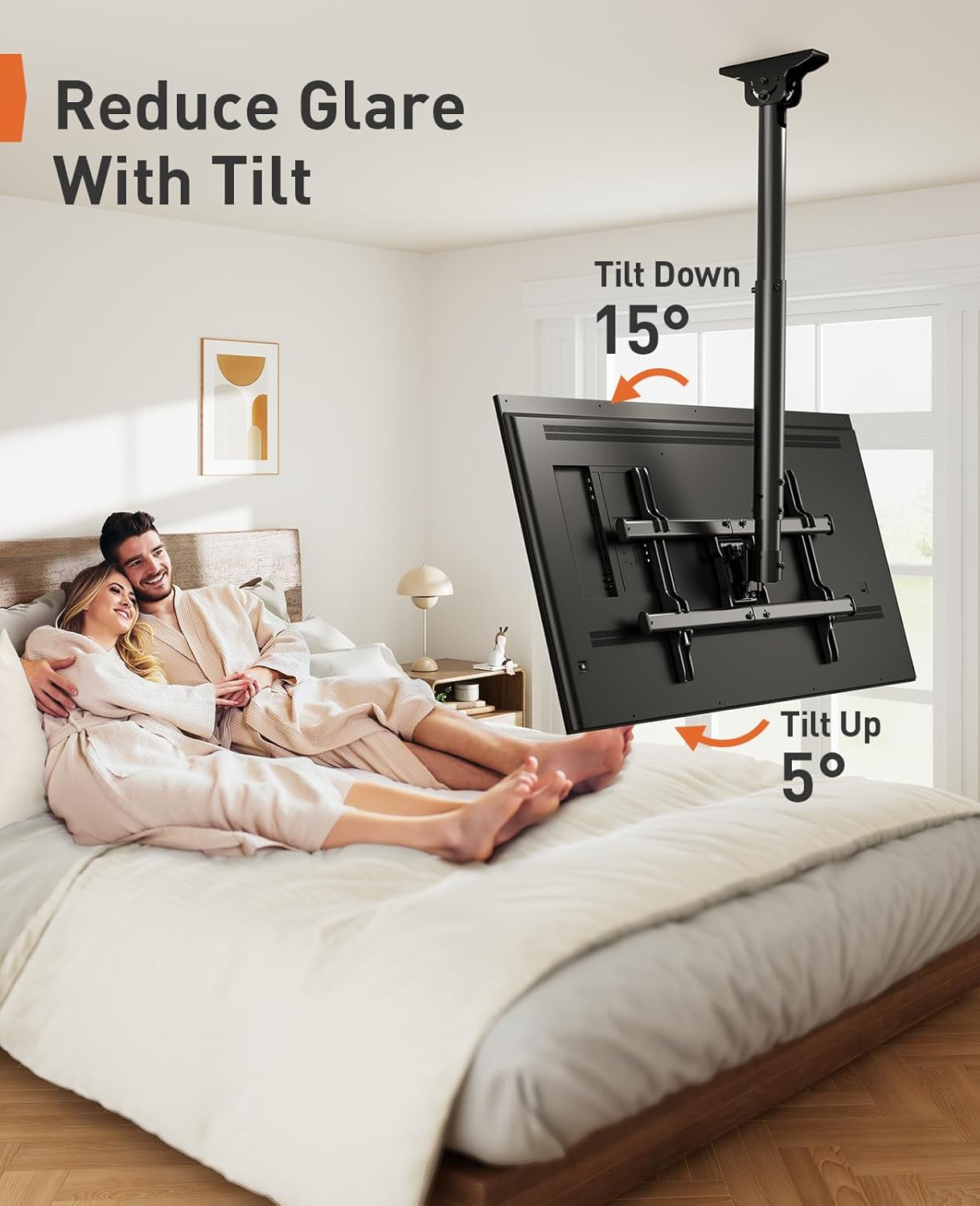
Image: How to reduce glare using the tilt function, showing the +5° and -15° tilt angles.
6.3 Swivel Adjustment
The TV mount can swivel 360° around the pole, allowing you to achieve an optimal view from any seat in the room. Simply rotate the TV to your preferred viewing direction.

Image: Achieving an optimal view from any seat with the 360° swivel feature.
6.4 Level Adjustment
After installation, you can fine-tune the TV's level by adjusting it +/-3°. This allows for minor corrections to ensure the TV is perfectly horizontal.

Image: Fine-tuning the TV's position with the +/-3° level adjustment after installation.
6.5 Cable Management
The ceiling mount is designed with a hollow tube for cable management. Route your TV cables through the pole to keep them hidden and maintain a neat appearance. Use the provided cable ties to secure cables if necessary.
7. Maintenance
- Regular Checks: Periodically check that all screws and connections are secure. Over time, vibrations or adjustments can cause screws to loosen.
- Cleaning: Clean the mount with a soft, dry cloth. Do not use abrasive cleaners or solvents, as they may damage the finish.
- Lubrication: No lubrication is required for the moving parts.
- Damage: If any part of the mount becomes damaged, do not use it. Contact customer support for replacement parts or professional inspection.
8. Troubleshooting
| Problem | Possible Cause | Solution |
|---|---|---|
| TV is not level after installation. | Minor misalignment during installation. | Use the +/-3° level adjustment feature to fine-tune the TV's horizontal position. |
| TV tilts downwards unexpectedly. | Tilt adjustment knobs are not tightened sufficiently. | Ensure the tilt adjustment knobs on the TV plate are securely tightened. Do not overtighten. |
| Mount feels unstable. | Screws are loose or incorrect installation. | Re-check all mounting screws on the ceiling plate and TV plate. Ensure they are tightened according to instructions. Verify ceiling type and proper anchor usage. If unsure, consult a professional. |
| Cannot adjust height of the pole. | Locking mechanism is too tight or jammed. | Loosen the locking mechanism completely. If still stuck, ensure no cables are obstructing the pole's movement. |
9. Warranty & Customer Support
Perlegear provides a limited warranty for this product. For detailed warranty information, please refer to the warranty card included with your purchase or visit the official Perlegear website.
If you encounter any issues during installation or use, or if you have any questions, please do not hesitate to contact Perlegear customer support:
- Website: www.perlegear.com (Example link, actual link may vary)
- Email: support@perlegear.com (Example email, actual email may vary)
- Phone: Please check the Perlegear website for regional contact numbers.
When contacting support, please have your product model number (PGLCM1) and purchase information ready.