
1. Introduction
This manual provides essential information for the safe and effective installation, operation, and maintenance of the TAKEX BUS-20XT Infrared Sensor. Please read this manual thoroughly before using the product and retain it for future reference.
2. Safety Information
Always observe the following safety precautions to prevent injury to yourself or others and to avoid damage to the device.
- Ensure the power supply is disconnected before installation or maintenance.
- Installation should be performed by qualified personnel to ensure proper wiring and mounting.
- Do not disassemble or modify the sensor. This may void the warranty and cause malfunction.
- Use only specified power voltage (DC10-28V).
- Avoid installing the sensor in locations with excessive vibration or direct exposure to corrosive substances.
3. Product Overview
The TAKEX BUS-20XT is an advanced infrared sensor designed for reliable outdoor perimeter security. It features a 2-beam opposed detection method with dual modulation for enhanced performance.
Key Features:
- Easy Wiring and Installation: Utilizes a 2-wire connection from the bus network controller for signal transmission, simplifying the installation process by eliminating the need for individual wiring.
- Strong Against External Interference: Incorporates a proprietary dual modulation method and photoelectric conversion circuit (patented technology) to significantly improve discrimination against external light sources such as direct sunlight or vehicle headlights, ensuring highly reliable outdoor security.
- Resistant to Harsh Environments: Equipped with a 2-stage high-power beam that offers a 100-fold sensitivity margin and a 10-fold distance margin. This design effectively reduces false alarms caused by adverse weather conditions like fog, snow, or heavy rain.
- Energy-Saving Design: Features reduced current consumption, which provides greater flexibility in power supply capacity and enables a more efficient overall system design.
- Green Design (RoHS Compliant): Manufactured with environmental considerations, adhering to the RoHS directive by excluding hazardous substances such as lead, mercury, cadmium, hexavalent chromium, polybrominated biphenyls, polybrominated diphenyl ethers, bis(2-ethylhexyl) phthalate, butyl benzyl phthalate, dibutyl phthalate, and diisobutyl phthalate.

Figure 1: General view of the TAKEX BUS-20XT Infrared Sensor.
4. Setup and Installation
Proper installation is crucial for optimal performance of the BUS-20XT sensor. Ensure the emitter and receiver units are mounted securely and aligned correctly.
4.1 Mounting
The sensor is designed for wiring-type installation. Refer to the external dimensions diagram for precise mounting hole locations and cable entry points.

Figure 2: External dimensions and mounting points of the BUS-20XT sensor. All dimensions are in millimeters.
4.2 Optical Axis Adjustment
Align the emitter and receiver units so that the infrared beam is precisely aimed at the receiver. The optical axis can be adjusted horizontally by ±95° and vertically by ±10°.

Figure 3: Illustration of the infrared beam path between the emitter and receiver. The detection range is within 20 meters, with a beam width of approximately 0.6 meters.
5. Wiring Diagram
The BUS-20XT sensor uses a 2-wire bus network connection for signal transmission. Ensure correct polarity when connecting the power and signal lines.

Figure 4: Wiring connections for the emitter and receiver units. The busline connections are (4) (+), (3) (-), (2) (+), (1) (-). Power consumption for the BUS-20XT emitter is 6mA and the receiver is 21mA. Refer to the table for maximum wiring distances based on wire size and voltage.
Important Wiring Notes:
- The maximum wiring distance from the controller to the farthest sensor is 1,000 meters.
- The total wiring length for the entire system must not exceed 4,000 meters.
- For busline signal wires, use AE wire (OP wire).
- There are no restrictions on the position or distribution count for busline distribution.
6. Operating Instructions
The BUS-20XT operates by detecting the interruption of its near-infrared beams. The sensor provides various indicators and functions for monitoring and adjustment.
6.1 Indicators
- Emitter Power Indicator: Green light (on when open, off when closed).
- Alarm/Receiver Sensitivity Indicator: Red light indicates alarm output. Red blinking indicates receiver sensitivity attenuation.
- Memory/Check Indicator: Functions as a memory indicator when the controller is in "operation mode" (red blinking during sensor control, red light during controller control). Functions as a check indicator when the controller is in "check mode" (red light upon alarm signal response).
6.2 Functions
- Modulation frequency switching function.
- Cover compensation function.
- Monitor output function.
- Detection response time adjustment function (0.05s, 0.1s, 0.25s, 0.7s).
- Sound check function.
- Alarm memory display function.
- Receiver sensitivity display function.
7. Maintenance
Regular maintenance ensures the longevity and reliable operation of your BUS-20XT sensor.
- Cleaning: Periodically clean the optical surfaces of both the emitter and receiver units with a soft, dry cloth to remove dust, dirt, or spiderwebs that may obstruct the beam. Do not use abrasive cleaners.
- Beam Alignment Check: Regularly verify that the emitter and receiver remain properly aligned. Misalignment can lead to false alarms or missed detections.
- Wiring Inspection: Periodically inspect all wiring for signs of wear, damage, or loose connections.
8. Troubleshooting
If you encounter issues with your BUS-20XT sensor, refer to the following common problems and solutions.
8.1 False Alarms
- Check Beam Alignment: Ensure the emitter and receiver are perfectly aligned. Use the sensitivity display function to assist.
- Clean Optical Surfaces: Dust, dirt, or insects on the lens can cause false alarms. Clean as described in Section 7.
- Environmental Factors: While designed for harsh environments, extreme fog, heavy snow, or rain can still affect performance. Adjust detection response time if necessary.
- External Light Interference: Although resistant, strong, direct external light might rarely cause issues. Re-check alignment or consider repositioning if possible.
8.2 No Detection
- Verify Power: Ensure the sensor is receiving power (green power indicator on emitter should be lit). Check for low voltage alarms.
- Check Wiring: Inspect all wiring connections for looseness or damage.
- Beam Obstruction: Ensure there are no physical obstructions blocking the beam path.
- Sensor Malfunction: If all other checks fail, the sensor may require professional inspection or replacement.
8.3 Tamper Alarm
- Check Covers: Ensure the covers of both the emitter and receiver units are securely closed and latched.
9. Specifications
Detailed technical specifications for the TAKEX BUS-20XT Infrared Sensor.
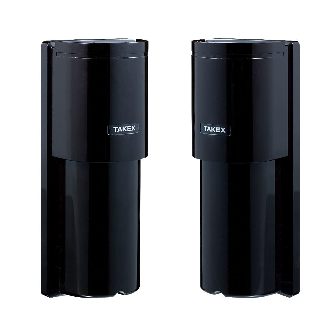
Figure 5: Official specification sheet for the TAKEX BUS-20XT Infrared Sensor.
| Item | Specification |
|---|---|
| Product Name | Infrared Sensor |
| Model No. | BUS-20XT |
| Detection Method | Near-infrared beam interruption (2-beam opposed type, Dual modulation method) |
| Detection Range | Indoor: 10m (20m max) Outdoor: 5m (20m max) |
| Detection Response Time | 0.05s, 0.1s, 0.25s, 0.7s (4 levels via setting switch) |
| Power Voltage | DC10-28V (with polarity) |
| Current Consumption | 20mA or less (max) |
| Transmission Method | Bus network method (Time-division multiplex transmission method) / (with polarity) |
| Transmission Signal | Alarm: Output according to alarm setting Tamper: Output when receiver cover is removed Low voltage: Output when power voltage drops |
| Emitter Indicator Light | Power indicator: Green light (on when open/off when closed) |
| Alarm/Receiver Sensitivity Indicator Light | Alarm output: Red light Receiver sensitivity attenuation: Red blinking |
| Memory/Check Indicator Light | Memory: Red blinking during sensor control (when controller is in "operation mode"), Red light during controller control Check: Red light upon alarm signal response (when controller is in "check mode") |
| Additional Functions | Modulation frequency switching, Cover compensation, Monitor output, Detection response time adjustment, Sound check, Alarm memory display, Receiver sensitivity display |
| Optical Axis Adjustment Range | Horizontal: ±95° Vertical: ±10° |
| Operating Ambient Temperature | -25°C to +60°C (non-condensing, non-freezing) |
| Installation Location | Indoor, Outdoor (Drip-proof structure, IP55 equivalent) |
| Connection Wiring | Dedicated bus network cable |
| Weight | Emitter: Approx. 370g Receiver: Approx. 400g |
| Appearance | Resin (Wine Red) |
10. Warranty and Support
TAKEX products are manufactured to high-quality standards. This product is covered by a limited warranty against defects in materials and workmanship. For specific warranty terms and conditions, please refer to the documentation provided with your purchase or contact your local TAKEX distributor.
Customer Support:
For technical assistance, troubleshooting, or service inquiries, please contact your authorized TAKEX dealer or visit the official TAKEX website for support resources.