1. Introduction
The DALY Smart BMS (Battery Management System) is designed for LiFePo4 15S 48V battery packs, providing essential protection and monitoring functions. This PCB (Printed Circuit Board) ensures the health and longevity of your battery pack by managing charging, discharging, and balancing processes. It features smart communication capabilities including UART, CAN, and Bluetooth for comprehensive battery monitoring and parameter adjustment.
2. Safety Information
Please read and understand all safety instructions before installation and operation. Failure to follow these instructions may result in electric shock, fire, or serious injury.
- Always disconnect power before performing any wiring or maintenance.
- Ensure correct polarity when connecting the BMS to the battery pack and load. Incorrect connections can damage the BMS and battery.
- Use appropriate personal protective equipment (PPE) such as insulated gloves and eye protection.
- Avoid short-circuiting the battery terminals or BMS connections.
- Do not expose the BMS to water or excessive humidity. While the BMS is waterproof and humidity resistant, direct exposure should be avoided.
- Only use the BMS with LiFePo4 battery cells that match the specified voltage and cell count (15S, 3.2V nominal per cell).
- Keep the BMS cooling surface uncovered to ensure proper heat dissipation.
3. Package Contents
Verify that all items are present in the package:
- DALY 3.2V LiFePo4 BMS (1 unit)
- Bluetooth Module (1 unit)
- NTC Temperature Sensor (1 unit)
- Sampling Cable (1 unit)
- UART Cable (1 unit)
- Instruction Manual (1 unit)

Image: Contents of the DALY Smart BMS package, including the BMS unit, cables, Bluetooth module, and instruction manual.
4. Product Overview
The DALY Smart BMS is a compact and robust unit designed for efficient battery management. It features multiple ports for communication and sensing.

Image: Front view of the DALY Smart BMS, showing the main terminals (B-, P-), and communication ports (NTC, Power board, UART, CAN/485).
Communication Interfaces
The BMS supports various communication protocols for monitoring and control:
- UART: Universal Asynchronous Receiver-Transmitter for serial communication, typically used for PC software connection.
- CAN: Controller Area Network, a robust vehicle bus standard for communication.
- RS485: A standard for serial communication, often used in industrial applications.
- Bluetooth (BT): For wireless connection to a smartphone application.
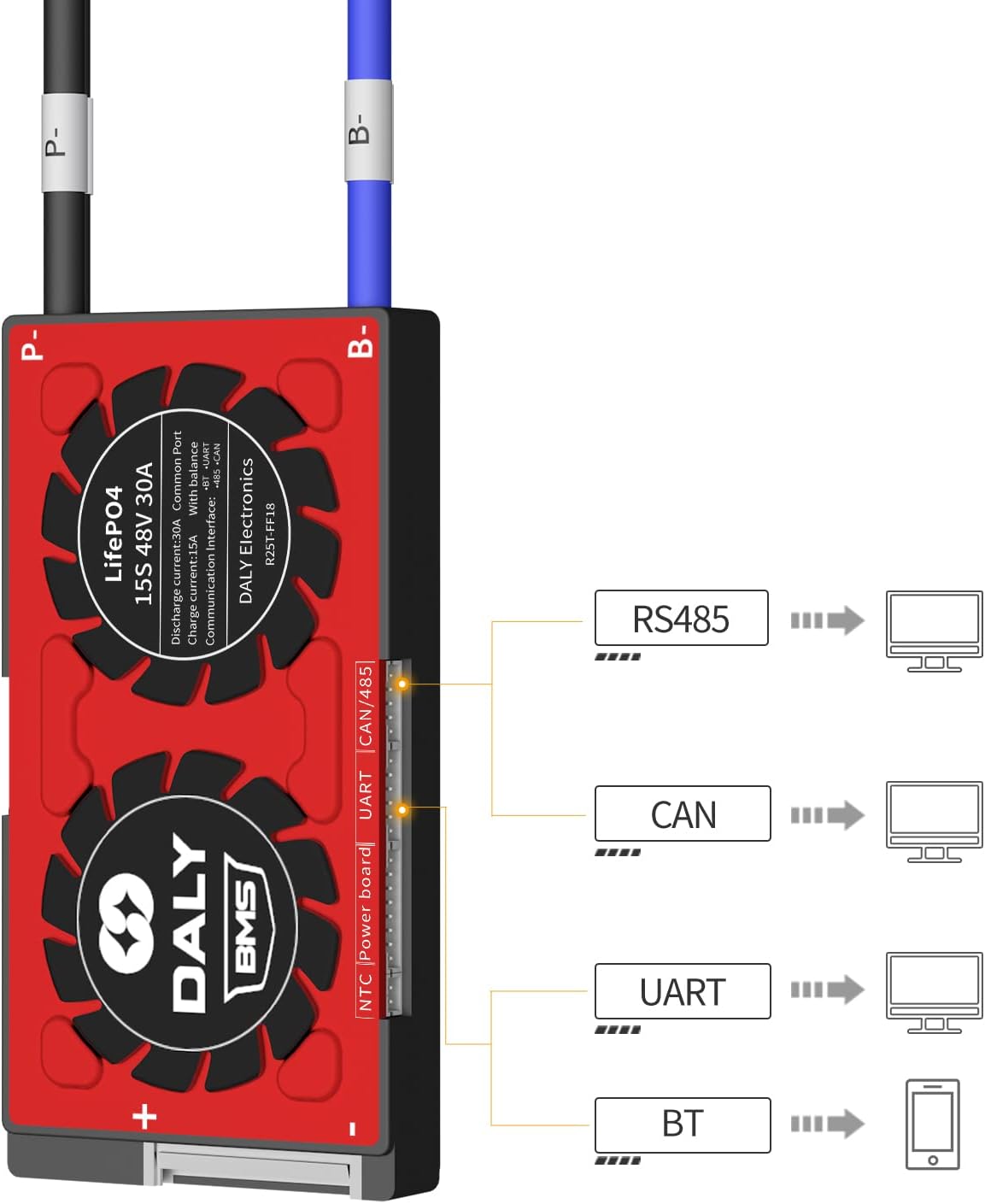
Image: Diagram illustrating the various communication interfaces (RS485, CAN, UART, BT) available on the DALY Smart BMS and their typical connections to external devices.
5. Specifications
Key technical specifications for the DALY Smart BMS LFP 15S 48V 30A:

Image: Detailed table of specifications for the DALY Smart BMS, including current ratings, voltage thresholds, and physical dimensions.
| Parameter | Value |
|---|---|
| Product Type | LiFePo4 15S 30A Common Port with Balance |
| Communications | UART/RS485/CAN |
| Discharge Current | 30A |
| Over-discharge Current | 45A |
| Charge Current | 15A |
| Overcharge Current | 45A |
| Overcharge Detect Voltage | 3.75V ± 0.05V (per string) |
| Overcharge Release Voltage | 3.65V ± 0.05V |
| Overcharge Protection Delay | 1s |
| Balance Detect Voltage | 3.2V |
| Balance Current | 35 ± 5 mA |
| Over-discharge Detect Voltage | 2.2V ± 0.1V (per string) |
| Over-discharge Detect Delay | 1s |
| Over-discharge Release Voltage | 2.3V ± 0.1V |
| Charge Voltage | S*3.65V (S = number of series cells) |
| BMS Self-Consumption Working Current | ≤20 mA |
| Dimensions (L x W x H) | 66 x 128 x 12 mm (approx. 2.6 x 5.04 x 0.51 inches) |
| Output Wire | 12AWG / 130mm |
| Balance Wires | 24AWG / 450mm |
6. Installation and Wiring
Careful wiring is critical for the correct operation and safety of the BMS and battery pack. Refer to the wiring diagram below.
Wiring Steps:
- Preparation: Gather necessary tools: soldering machine (suggested 662°F/350°C), scissors, double-sided tape, tin wire, and multimeter.
- Balance Wires: Before connecting the black and red balance wires to the battery pack, you must disconnect the balance wires from the BMS connector. This prevents accidental short circuits during installation.
- BMS Placement: Ensure the BMS cooling surface side is uncovered to allow for proper heat dissipation.
- Connect Balance Wires: Connect the DALY matching balance wires (regular length 450 mm / 17.72 inches) to each cell of your 15S LiFePo4 battery pack, starting from the negative terminal (B-) and progressing upwards to the positive terminal (B+). Ensure each wire is connected to the correct cell tap.
- Connect BMS Connector: After confirming all balance wires are correctly welded and installed, connect the balance wire connector to the BMS.
- Main Power Connections: Connect the main negative terminal of the battery pack to the B- terminal on the BMS. Connect the main positive terminal of the battery pack to the P- terminal on the BMS. The P- terminal will serve as the common negative output for both charging and discharging.
- Load/Charger Connection: Connect your motor/load and charger to the P- terminal (common negative) and the main positive terminal of the battery pack.
- Communication Modules: Connect the Bluetooth module, NTC sensor, and UART/CAN/RS485 cables to their respective ports on the BMS as needed.

Image: Comprehensive wiring diagram for the DALY Smart BMS, showing connections for the battery pack, load, charger, and communication modules (Bluetooth, UART, CAN, RS485).
Initial Activation:
There are two methods to activate the BMS for the first time:
- Press the activation button on the battery board.
- Connect a charger to the battery pack to initiate charging.
7. Operating the Smart BMS
The DALY Smart BMS allows for real-time monitoring and parameter adjustment via a Bluetooth app or PC software.
Bluetooth App Connection:
- Ensure the Bluetooth module is connected to the BMS.
- Download the DALY BMS app from your smartphone's app store.
- Enable Bluetooth on your smartphone and open the DALY BMS app.
- The app will scan for available BMS devices. Select your BMS from the list to connect.
- The initial password for the Smart Board APP to change parameters is 123456.

Image: DALY Smart BMS connected to a smartphone via Bluetooth, displaying the app interface with battery status and monitoring data.
PC Software Connection:
For detailed monitoring and advanced parameter settings, connect the BMS to a PC using the UART cable.
- Connect the UART cable from the BMS to your PC.
- Install the DALY BMS PC software (available from the DALY website).
- Open the software and establish a connection with the BMS.
The serial number of the BMS and the protection parameters (Li-ion, LiFePo4) have default values from the factory. The capacity of the battery pack needs to be set according to the actual capacity (AH) of the battery pack. If the capacity AH is not set correctly, the percentage of remaining power will be inaccurate. Other parameters can also be set to your needs.
Online Tutorials:
For detailed connection tutorials, visit the DALY website: https://www.dalyelec.cn/newsshow.php?cid=25&id=78&lang=1. This page includes tutorials for:
- DALY Smart BMS Touch Screen Connection Tutorial
- DALY Smart BMS SOC Light Board Connection Tutorial
- DALY Smart BMS PC Screen Connection Tutorial
- DALY Smart BMS CANBUS Connection Tutorial
- DALY Smart BMS Bluetooth APP Connection Tutorial
- DALY Smart BMS UART, RS485 Connection Tutorial
8. Maintenance
Proper maintenance ensures the longevity and optimal performance of your DALY Smart BMS and battery pack.
- Regular Inspection: Periodically check all wiring connections for tightness and signs of corrosion or damage.
- Cleanliness: Keep the BMS and its surroundings clean and free from dust and debris. Use a dry, soft cloth for cleaning.
- Ventilation: Ensure the BMS has adequate ventilation and its cooling surface is not obstructed.
- Software Updates: Check for and apply any available firmware or software updates for the BMS app or PC software to ensure optimal performance and access to new features.
- Storage: If storing the battery pack and BMS for an extended period, ensure the battery is at a suitable storage voltage (typically around 50% charge) and stored in a cool, dry place.
9. Troubleshooting
This section addresses common issues you might encounter with your DALY Smart BMS.
- BMS Not Activating:
Possible Cause: BMS not properly activated.
Solution: Press the activation button on the BMS board or connect a charger to the battery pack to initiate charging. - No Power Output:
Possible Cause: Over-discharge protection triggered, short circuit, or incorrect wiring.
Solution: Check battery voltage; if below over-discharge threshold, charge the battery. Inspect all wiring for correct connections and potential short circuits. - Charging Not Working:
Possible Cause: Overcharge protection triggered, charger fault, or incorrect wiring.
Solution: Check individual cell voltages; if any cell is above the overcharge threshold, the BMS will prevent further charging. Verify charger functionality and wiring. - Bluetooth Connection Issues:
Possible Cause: Bluetooth module not connected, app issues, or interference.
Solution: Ensure the Bluetooth module is securely connected to the BMS. Restart the app and your phone's Bluetooth. Try connecting in an area with less wireless interference. - Inaccurate State of Charge (SOC) Reading:
Possible Cause: Battery pack capacity (AH) not correctly set in the app/software.
Solution: Connect via Bluetooth app or PC software and adjust the battery pack's AH capacity to its actual value. - BMS Overheating:
Possible Cause: Excessive current, poor ventilation, or internal fault.
Solution: Reduce load current. Ensure the BMS cooling surface is uncovered and has adequate airflow. If overheating persists, discontinue use and contact support.
10. Warranty and Support
DALY is committed to providing high-quality products and customer satisfaction.
We offer 24-hour one-on-one customer service and lifetime technical support for your DALY Smart BMS. If you encounter any issues or have questions not covered in this manual, please do not hesitate to contact our support team.
For specific inquiries regarding active balancers, parallel modules, or other accessories, please contact our online customer service.