1. Introduction
This manual provides essential information for the safe and efficient operation of the IFME DP2200 Analog Output Sensor Amplifier. The DP2200 is designed as an evaluation system and display for analog signals, featuring robust industrial connectivity and an integrated LED indicator. Please read this manual thoroughly before installation and operation.
2. Safety Instructions
Warning: Failure to follow these safety instructions may result in personal injury or damage to the device.
- Installation, electrical connection, setup, programming, operation, and maintenance of the device must be carried out by qualified personnel only.
- Ensure that the power supply is disconnected before performing any installation or wiring work.
- Protect the device and cables from mechanical damage.
- Do not operate the device in environments exceeding its specified operating conditions.
- Use only original accessories and spare parts to ensure proper function and safety.
3. Product Overview
The IFME DP2200 is an Analog Output Sensor Amplifier designed for industrial applications. It processes sensor input signals and provides both digital and analog outputs. The device features M12 connectors for reliable and secure connections in demanding environments.
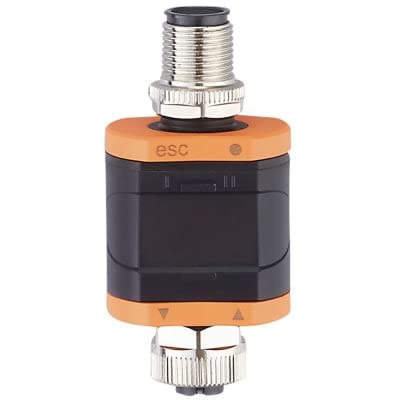
Image showing the IFME DP2200 Analog Output Sensor Amplifier, a compact industrial device with M12 connectors at both ends and an orange and black housing.
Key Features:
- Input: Sensor: 24VDC, AI: 4-20mA, M12 F 5p connector
- Output: 1 Digital Output (NO/NC), 1 Analog Output (4-20mA), M12 M 4p connector
- Integrated LED indicator for status feedback
- Durable copper material construction
4. Setup
4.1 Mounting
Mount the DP2200 in a location that is easily accessible for wiring and observation of the LED indicator. Ensure the mounting position is stable and free from excessive vibration or heat sources. Consider the cable routing to prevent strain on the M12 connectors.
4.2 Wiring
Before connecting, ensure all power supplies are disconnected. Refer to the following for proper wiring:
- Sensor Input (M12 F 5p): Connect your 24VDC sensor with 4-20mA analog output to this port. Ensure correct pin assignment according to your sensor's documentation.
- System Output (M12 M 4p): Connect this port to your control system or display unit. This port provides one digital output (normally open/normally closed configurable) and one 4-20mA analog output. Verify pin assignments for your specific application.
After all connections are made, secure the M12 connectors firmly to ensure a reliable and sealed connection.
5. Operating Instructions
Once the DP2200 is correctly wired and powered, it will begin to evaluate the incoming analog signals from the connected sensor. The integrated LED indicator provides visual feedback on the device's status and operation.
- Power On: Apply 24VDC power to the sensor input side. The LED should illuminate, indicating power.
- Signal Evaluation: The device continuously processes the 4-20mA analog input.
- Output Monitoring: Monitor the 4-20mA analog output and the digital output (DO) on your control system to verify correct signal transmission and switching status.
Specific configuration details for the digital output (NO/NC) may require further reference to the manufacturer's detailed product sheet or programming guide, if applicable.
6. Maintenance
The IFME DP2200 is designed for minimal maintenance. Regular inspection and cleaning are recommended to ensure optimal performance and longevity.
- Cleaning: Periodically clean the exterior of the device with a soft, damp cloth. Do not use abrasive cleaners, solvents, or harsh chemicals, as these can damage the housing.
- Inspection: Regularly check all cable connections for tightness and signs of wear or damage. Ensure the M12 connectors are securely fastened.
- No User-Serviceable Parts: The device contains no user-serviceable parts. Do not attempt to open or repair the unit, as this will void the warranty.
7. Troubleshooting
If you encounter issues with your DP2200, perform the following basic checks:
- No Power/LED Off:
- Verify that the 24VDC power supply is active and correctly connected to the input M12 connector.
- Check for any breaks or damage in the power supply cable.
- Incorrect Analog Output:
- Ensure the sensor connected to the input is functioning correctly and providing a valid 4-20mA signal.
- Check the wiring between the DP2200 output and your control system for continuity and correct polarity.
- Verify the scaling or configuration settings on your receiving control system.
- Digital Output Not Switching:
- Confirm the input analog signal is within the expected range for the digital output to trigger.
- Check the wiring of the digital output to your control system.
- If configurable, verify the NO/NC setting of the digital output.
For persistent issues or complex problems, please contact IFME technical support or your local distributor.
8. Specifications
| Parameter | Value |
|---|---|
| Model Number | DP2200 |
| Brand | IFME |
| Manufacturer | IFM EFECTOR |
| Input (Sensor) | 24VDC, AI: 4-20mA, M12 F 5p |
| Output | 1 DO NO/NC, 1 AO 4-20mA, M12 M 4p |
| Material | Copper |
| ASIN | B0B61VG7NL |
| UPC | 705514667243 |
| Date First Available | July 7, 2022 |
9. Warranty and Support
For warranty information, please refer to the official IFME website or contact your point of purchase. Standard warranty terms typically cover manufacturing defects for a specified period from the date of purchase.
For technical support, product inquiries, or assistance with troubleshooting beyond the scope of this manual, please contact IFME customer service or your authorized IFME distributor. Contact details can usually be found on the manufacturer's official website.