
Introduction
This manual provides detailed instructions for the Hosyond 3.5 inch 480x320 TFT Touch Screen Module LCD Display Shield. This module is designed for seamless integration with Arduino R3 and Mega2560 development boards, offering a 3.5-inch resistive touch display with an integrated SD card socket. It features an 8-bit parallel interface for fast refresh rates and on-board level shifting for 5V/3.3V compatibility.
Product Features
- Supports development boards such as Arduino R3 and Mega2560 for direct plug-in use without additional wiring.
- Features a 480x320 resolution for clear display.
- Supports 16-bit RGB 65K color display, providing rich colors.
- Utilizes an 8-bit parallel bus for faster refresh rates compared to serial SPI.
- Resistive touch screen functionality for interactive applications.
- Includes an SD card slot for easy expansion and data storage.
- Equipped with an on-board 5V/3.3V level shifting IC, ensuring compatibility with both 5V and 3.3V operating voltages.
Package Contents
The package includes the following items:
- 1 x 3.5 inch TFT Touch Screen Module
- 1 x Touch Pen
Setup
The Hosyond 3.5 inch TFT Touch Screen Module is designed as a shield for direct connection to compatible Arduino boards. Follow these steps for initial setup:
- Prepare your Arduino Board: Ensure your Arduino R3 or Mega2560 board is powered off before connecting the display shield.
- Align the Shield: Carefully align the pins of the 3.5 inch TFT Touch Screen Module with the corresponding headers on your Arduino R3 or Mega2560 board. The shield is designed to plug directly into the Arduino headers.
- Connect the Shield: Gently press the display shield onto the Arduino board until all pins are securely seated. No additional wiring is typically required for basic display and touch functionality.
- Power On: Connect your Arduino board to a power source (e.g., USB or external power supply). The display should initialize.

Software Setup: To utilize the display and touch features, you will need to install appropriate libraries in your Arduino IDE. Common libraries for ILI9486 driver ICs and resistive touchscreens include TFT_eSPI or Adafruit_TFTLCD, and a touch screen library like Adafruit_TouchScreen. Some users have reported success with the MCU_Friend library for this specific screen.
Operating Instructions
Display Functionality
Once the display shield is correctly connected and the necessary libraries are installed and configured in your Arduino sketch, you can begin programming the display. The 480x320 resolution and 16-bit color support allow for a wide range of graphical applications. Refer to the documentation of your chosen display library for specific functions to draw shapes, text, and images.
Touch Screen Operation
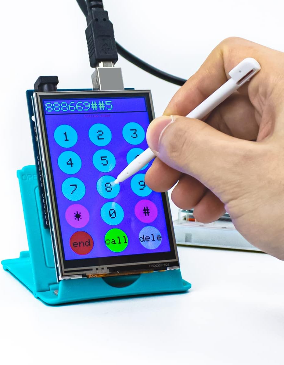
The module features a resistive touch screen. Use the included touch pen or a similar stylus for optimal interaction. The touch screen allows for user input, enabling interactive menus, buttons, and drawing applications. Calibration may be required for accurate touch response, which is typically handled by the touch screen library.
SD Card Socket Usage
The integrated SD card socket allows for external data storage, such as images, fonts, or logging data. To use the SD card functionality, insert a formatted microSD card into the slot. You will need to use the Arduino SD library in your sketch to read from and write to the card. Ensure the correct chip select (CS) pin for the SD card is configured in your code (often pin 10 or 53 on Mega, depending on the library and board configuration).
Pinout Diagram
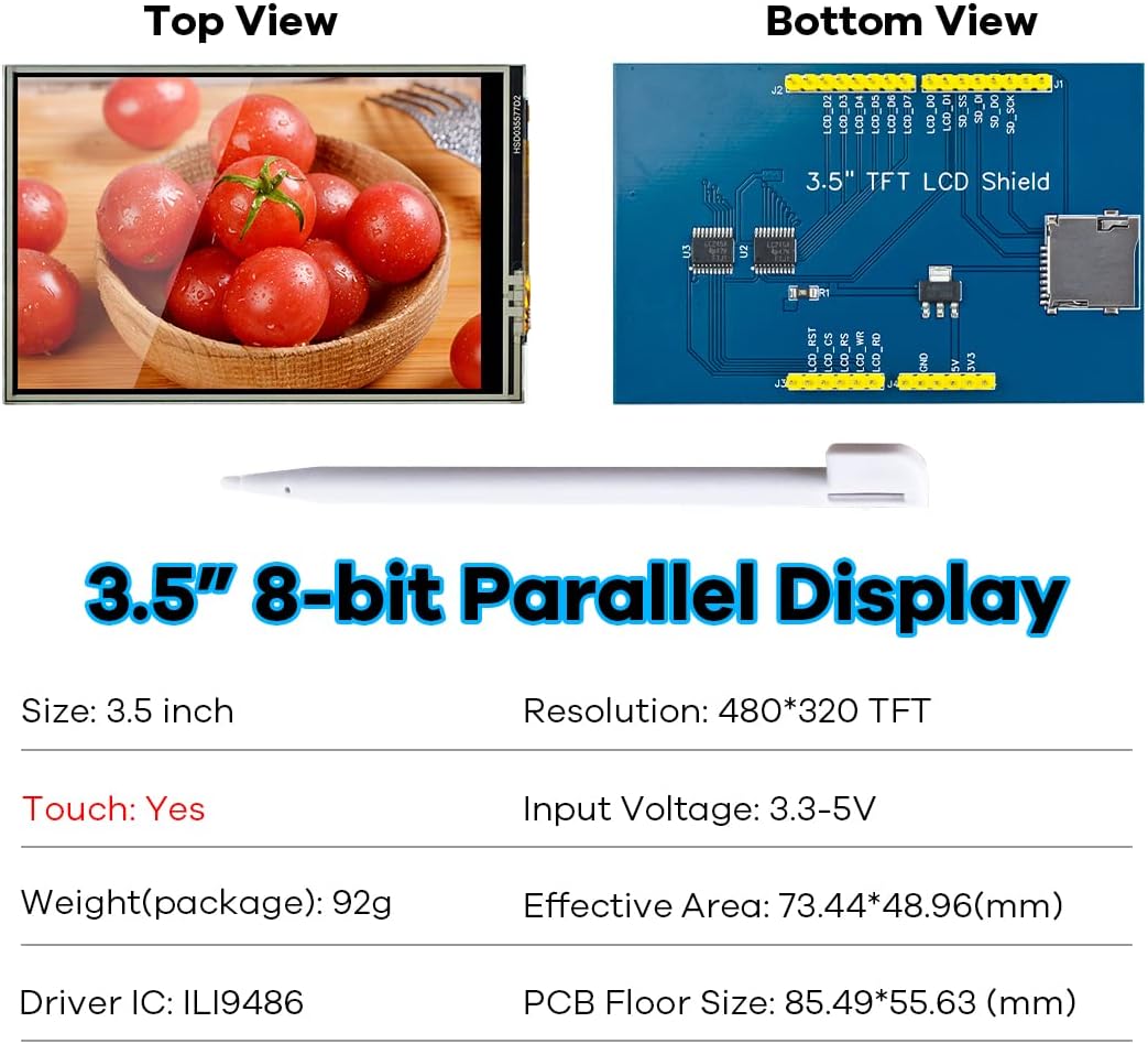
Understanding the pin connections is crucial for advanced usage and troubleshooting. The module utilizes an 8-bit parallel interface for the LCD and an SPI interface for the SD card. Below is a description of the key pins:

| Pin Label | Pin Description |
|---|---|
| LCD_RST | LCD bus reset signal (low level reset) |
| LCD_CS | LCD bus chip select signal (low level enable) |
| LCD_RS | LCD bus command / data selection signal (low level: command, high level: data) |
| LCD_WR | LCD bus write signal |
| LCD_RD | LCD bus read signal |
| GND | Power ground |
| 5V | 5V power input |
| 3V3 | 3.3V power input (this pin can be disconnected) |
| LCD_D_X | LCD 8-bit data Bit_X (D0-D7) |
| SD_SS | SD card SPI bus chip select signal (low level enable) |
| SD_DI | SD card SPI bus MOSI signal |
| SD_DO | SD card SPI bus MISO signal |
| SD_SCK | SD card SPI bus clock signal |
Maintenance
To ensure the longevity and optimal performance of your Hosyond TFT Touch Screen Module, follow these maintenance guidelines:
- Cleaning: Use a soft, dry, anti-static cloth to clean the screen surface. For stubborn smudges, lightly dampen the cloth with distilled water or a screen-safe cleaner. Avoid abrasive materials or harsh chemicals.
- Handling: Handle the module by its edges to avoid touching the screen surface or the electronic components on the PCB.
- Storage: When not in use, store the module in a cool, dry place, away from direct sunlight and extreme temperatures. Keep it in its original packaging or an anti-static bag to prevent dust accumulation and electrostatic discharge.
- Power: Always disconnect power from your Arduino board before connecting or disconnecting the display shield to prevent damage to the components.
Troubleshooting
If you encounter issues with your Hosyond TFT Touch Screen Module, consider the following troubleshooting steps:
- Display Not Lighting Up:
- Ensure the shield is correctly and firmly seated on the Arduino board.
- Verify that the Arduino board is receiving adequate power.
- Check your Arduino sketch for correct initialization of the display library and pin assignments.
- Incorrect Colors or Graphics:
- Confirm that you are using the correct display driver IC (ILI9486) in your library configuration.
- Ensure the display library is up to date.
- Touch Screen Not Responding or Inaccurate:
- Verify that the touch screen library is correctly installed and initialized.
- Perform a touch screen calibration. Many touch libraries include example sketches for calibration.
- Check the power supply voltage. Inconsistent touch response can occur if the voltage is slightly off (e.g., 5.3V instead of 5V). A small resistor in series with the 5V line might help stabilize the voltage if it's too high.
- Ensure the touch screen coordinates are correctly mapped in your code, especially if the display orientation is changed. The physical 0/0 point of the touchscreen might differ from the display's 0/0 point.
- SD Card Not Initializing:
- Ensure the SD card is properly inserted and formatted (FAT16 or FAT32).
- Verify the correct chip select (CS) pin for the SD card is defined in your Arduino sketch (e.g., pin 10 or 53 for Mega).
- Check for conflicts with other libraries or components using SPI.
- Try a different SD card to rule out card issues.
Specifications
Detailed technical specifications for the Hosyond 3.5 inch 480x320 TFT Touch Screen Module:
| Feature | Detail |
|---|---|
| Display Color | RGB 65K color |
| Screen Size | 3.5 inches |
| Display Type | TFT |
| Touch Screen Type | Resistive |
| Driver IC | ILI9486 |
| Resolution | 480x320 pixels |
| Module Interface | 8-bit parallel interface |
| Active Area | 73.44 x 48.96 mm |
| Module PCB Size | 85.49 x 55.63 mm |
| Operating Temperature | -20℃ to 70℃ |
| Storage Temperature | -40℃ to 70℃ |
| Operating Voltage | 5V / 3.3V |
| Item Weight | 55g (with touch pen) / ~2 ounces |
| Compatible Boards | Arduino R3, Arduino Mega2560 |
| Connectivity | SD Card Socket |
Warranty and Support
Hosyond is committed to providing reliable products and customer service. For support, technical inquiries, or warranty information, please refer to the official Hosyond website or contact their customer service channels. Keep your purchase receipt for warranty claims.