1. Introduction
The Generic Raspberry Pi Compute Module 4 IO Board is a development platform and reference base-board designed for use with the Raspberry Pi Compute Module 4 (CM4), which is sold separately. This board facilitates the integration and testing of the CM4 in various applications, serving as a versatile tool for both development and embedding into final products.
It allows users to quickly assemble a system using readily available components, including Raspberry Pi HATs and PCIe modules, to create custom solutions.
2. Product Overview and Features
The Compute Module 4 IO Board provides a comprehensive set of interfaces and features to support the full capabilities of the Raspberry Pi Compute Module 4. It is compatible with all versions of the Compute Module 4.
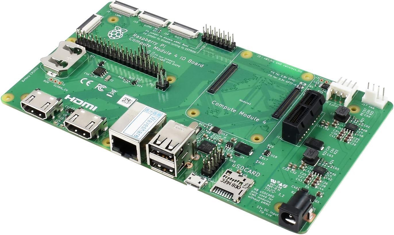
Figure 2.1: Angled view of the Raspberry Pi Compute Module 4 IO Board, showcasing various ports and components.
Key features include:
- CM4 Socket: Compatible with all variants of Compute Module 4.
- Standard Raspberry Pi HAT support: Allows connection of various HATs.
- Standard PCIe Gen 2 x1 socket: For connecting PCIe expansion cards.
- Dual MIPI DSI display interface: Two 22-pin 0.5 mm pitch cable connectors for displays.
- Dual MIPI CSI-2 camera interface: Two 22-pin 0.5 mm pitch cable connectors for cameras.
- USB Interfaces: Two USB 2.0 connectors and a micro USB socket for updating Compute Module 4.
- Gigabit Ethernet: RJ45 port with PoE support.
- SD Card Slot: For Compute Module 4 Lite (without eMMC) variants.
- Real-time clock (RTC): With battery socket for timekeeping and wake-up functionality.
- Fan Header: Standard fan connector.
- Various jumpers: To disable eMMC boot, disable wireless, and other specific features.

Figure 2.2: Top-down view of the IO Board, illustrating the placement of key components and connectors.
3. Setup
Follow these steps to set up your Compute Module 4 IO Board:
- Install Compute Module 4: Carefully align your Compute Module 4 with the CM4 socket on the IO Board and press it firmly into place. Ensure it is seated correctly.
- Insert SD Card (CM4 Lite only): If you are using a Compute Module 4 Lite (without eMMC), insert a microSD card with a pre-installed operating system into the dedicated SD card slot.
- Connect Peripherals:
- Display: Connect your display(s) to the HDMI ports or MIPI DSI connectors.
- Camera: Connect MIPI CSI-2 cameras to the camera interfaces.
- USB Devices: Plug in your keyboard, mouse, or other USB devices into the USB 2.0 ports.
- Network: Connect an Ethernet cable to the Gigabit Ethernet port for network access.
- Fan: If using an external fan, connect it to the fan header.
- PCIe Devices: If applicable, install your PCIe expansion card into the PCIe Gen 2 x1 socket.
- Power Connection: Connect a 12V / 5V DC power supply to the DC power input jack. Ensure the power supply meets the board's requirements.
- Jumper Configuration: Depending on your specific use case, you may need to configure jumpers. For example, to disable eMMC boot or wireless functionality. Refer to the official Raspberry Pi documentation for detailed jumper settings.
4. Operating Instructions
Once the board is set up, you can begin operating your Compute Module 4 IO Board:
- Power On: Apply power to the board. The CM4 should boot up according to the installed operating system.
- Operating System: The Compute Module 4 requires an operating system, typically Raspberry Pi OS. For CM4 Lite, this is installed on the microSD card. For CM4 with eMMC, the OS is flashed directly to the eMMC storage. Refer to the official Raspberry Pi documentation for OS installation and flashing procedures.
- Interface Usage:
- HDMI: Use standard HDMI cables to connect to monitors.
- USB: Standard USB devices will function as expected.
- Ethernet: Provides wired network connectivity.
- CSI/DSI: These interfaces are for specific camera and display modules, requiring appropriate drivers and software configuration.
- PCIe: Ensure compatible drivers are installed for any PCIe expansion cards.
- Real-Time Clock: The onboard RTC can be configured to keep accurate time, even when the board is powered off, provided a battery is installed in the RTC socket.
5. Maintenance
Proper maintenance ensures the longevity and reliable operation of your Compute Module 4 IO Board:
- Environmental Conditions: Operate the board in a clean, dry environment, away from extreme temperatures, humidity, and direct sunlight.
- Cleaning: Use a soft, dry brush or compressed air to remove dust from the board. Avoid using liquids or abrasive cleaners.
- Static Discharge: Always handle the board by its edges and take precautions against electrostatic discharge (ESD) to prevent damage to sensitive components.
- Firmware and Software Updates: Regularly update the operating system and any installed software to ensure optimal performance and security. Refer to official Raspberry Pi documentation for update procedures.
- Power Supply: Use only a compatible and stable power supply to prevent damage.
6. Troubleshooting
If you encounter issues with your Compute Module 4 IO Board, consider the following troubleshooting steps:
- No Power/No Boot:
- Verify the power supply is correctly connected and providing the correct voltage (12V / 5V).
- Ensure the Compute Module 4 is properly seated in its socket.
- If using CM4 Lite, check if the microSD card is inserted correctly and contains a valid OS image.
- Check jumper settings, especially those related to eMMC boot.
- No Display Output:
- Ensure HDMI cables are securely connected to both the board and the monitor.
- Test with a different monitor or cable if possible.
- Verify the display resolution and refresh rate are supported by your monitor and configured correctly in the OS.
- USB Devices Not Detected:
- Try connecting the USB device to a different port.
- Ensure the device is functioning correctly on another computer.
- Check for any power-related issues if using high-power USB devices.
- Network Connectivity Issues:
- Check the Ethernet cable connection.
- Verify router/switch functionality.
- Ensure network drivers are installed and configured in the OS.
For more detailed troubleshooting, consult the official Raspberry Pi documentation and community forums.
7. Specifications
The following table outlines the technical specifications of the Compute Module 4 IO Board:

Figure 7.1: Diagram illustrating the board's interfaces and a table detailing its specifications.
| Feature | Description |
|---|---|
| CM4 Socket | Suitable for all variants of Compute Module 4 |
| Connectors | Standard Raspberry Pi HAT with PoE support, Standard PCIe Gen 2 x1 socket, Various jumpers to disable specific features (e.g., wireless connectivity, EEPROM writing) |
| RTC | Real-time clock with battery socket and ability to wake Compute Module 4 |
| Video | 2 x MIPI DSI display FPC connectors (22-pin 0.5 mm pitch cable) |
| Camera | 2 x MIPI CSI-2 camera FPC connectors (22-pin 0.5 mm pitch cable) |
| USB | 2 x USB 2.0 connectors, Micro USB socket for updating Compute Module 4 |
| Ethernet | Gigabit Ethernet RJ45 with PoE support |
| Storage Socket | MicroSD card socket for Compute Module 4 Lite (without eMMC) variants |
| Fan | Standard fan connector |
| Power Input | 12V / 5V DC |
| Dimensions | 160 x 90 mm |
| Item Weight | 3.87 ounces (0.11 Kilograms) |
| Hardware Interface | USB |
| Compatible Devices | Personal Computer, Laptop, Monitor, Printer, Router, Camera, Display |
8. Warranty and Support
For technical support, warranty information, and further documentation, please refer to the official Raspberry Pi website and community resources. As this is a development board, support is primarily provided through community forums and official documentation.
Note: This product is manufactured by Generic and is designed for use with the Raspberry Pi Compute Module 4. Any warranty claims or support requests should be directed to the respective manufacturer or vendor.


