1. Introduction
This manual provides detailed instructions for the NOYITO PC817 1-Channel Optocoupler Isolation Module. This module is designed to provide signal isolation and anti-interference capabilities in various electronic applications. It utilizes optocoupler technology for stable and reliable operation, protecting sensitive circuits from interference and voltage differences.

Figure 1: Two NOYITO PC817 1-Channel Optocoupler Isolation Modules, showing the top view with screw terminals and the PC817 chip.
2. Product Features
- Optocoupler Isolation: Employs optocoupler technology for stable and reliable signal isolation, ensuring long service life.
- Easy Wiring: Features 5.0 pitch screw terminals for convenient and secure wiring connections.
- Circuit Protection: Protects microcontroller circuits from interference when driving inductive loads such as motors.
- Signal Inversion Capability: Can function as an inverter to reverse input signal logic.
- High-Voltage Detection: Suitable for isolating and detecting high-voltage signals, for example, converting a 12V sensor output to a 5V microcontroller input.
- Current Amplification: Can amplify output current from microcontrollers to drive circuits requiring higher current.
3. Specifications
3.1. Module Parameters
- Input Signal Voltage: 3-5V, 12V, or 24V (variant dependent). This manual covers the 3-5V version.
- Output Signal Voltage: Wide voltage range, suitable for DC 1.8V to 24V.
- Module Dimensions (LWH): 66mm x 16.5mm x 12mm.
- Module Weight: Approximately 5 grams.
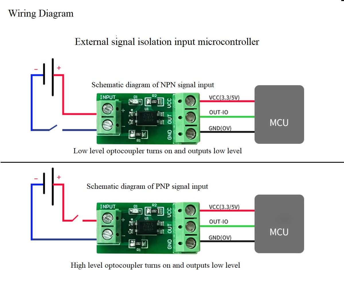
Figure 2: Module dimensions and identification of input/output terminals and optocoupler component.
3.2. PC817 Optocoupler Characteristics
- Isolation Voltage: Greater than 3000V.
- Maximum Input Current: 50mA.
- Working Current: Greater than 1mA.
- Maximum Output Current: 50mA (requires input current of 15-20mA).
- Operating Temperature: -55°C to +110°C.
- Maximum Signal Frequency: 5KHz.
4. Setup and Wiring
The NOYITO PC817 module features clearly labeled screw terminals for input and output connections. Proper wiring is essential for correct operation and safety.
4.1. Terminal Identification
- Input Side: Marked "INPUT" with "+" and "-" terminals. Connect your control signal source here.
- Output Side: Marked "VCC", "OUT", and "GND".
- VCC: Power supply for the output side (DC 1.8V - 24V).
- OUT: Isolated output signal.
- GND: Ground for the output side.

Figure 3: Top view of the module, highlighting the input and output screw terminals.
4.2. Basic Wiring Diagram
The following diagrams illustrate common wiring configurations for connecting the optocoupler module to a microcontroller (MCU) for signal isolation.
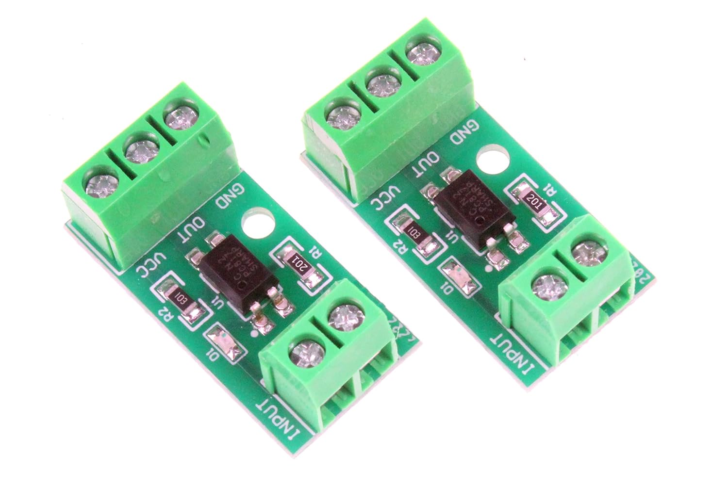
Figure 4: Wiring diagrams for NPN and PNP signal inputs to a microcontroller, demonstrating low-level optocoupler turn-on and output.
- NPN Signal Input (Low Level Trigger): Connect the positive of your input signal to the '+' terminal and the negative to the '-' terminal on the INPUT side. On the output side, connect VCC to your microcontroller's VCC (e.g., 3.3V/5V), GND to the microcontroller's GND, and OUT to an input pin on your microcontroller. When the input signal is low, the optocoupler turns on, and the output will be low.
- PNP Signal Input (High Level Trigger): Similar connections as NPN, but the optocoupler turns on when the input signal is high, and the output will be low.
4.3. Schematic Diagrams for Controller Isolation
These diagrams provide more detailed schematics for various isolation control scenarios with different signal types (NPN/PNP) and output configurations (NPN/PNP).

Figure 5: Detailed schematic diagrams illustrating NPN and PNP signal isolation control for various output configurations (NPN and PNP).
Refer to Figure 5 for specific connections based on your application's requirements for NPN or PNP signal isolation and desired output behavior (active low or active high).
5. Operating Principles
The PC817 optocoupler module operates on the principle of optical isolation. An internal LED on the input side emits light when current flows through it, which is then detected by a phototransistor on the output side. This optical link electrically separates the input and output circuits, preventing electrical noise, ground loops, and voltage spikes from transferring between them.
When a signal is applied to the input terminals, the LED illuminates, causing the phototransistor to conduct. This conduction changes the state of the output signal. The output circuit is powered independently via the VCC and GND terminals on the output side, allowing it to operate at a different voltage level than the input circuit.
6. Applications
The versatility of the NOYITO PC817 Optocoupler Isolation Module makes it suitable for a range of applications:
- Microcontroller Protection: Isolating microcontrollers from high-power or noisy inductive loads like motors, relays, or solenoids.
- Signal Level Shifting: Converting signal voltage levels, for instance, from a 12V sensor to a 5V microcontroller input.
- Noise Reduction: Eliminating common-mode noise and ground loops in industrial control systems.
- PLC Interface: Adapting signals for Programmable Logic Controllers (PLCs) that require specific voltage inputs (e.g., converting a low-voltage signal to a 24V PLC input).
- Current Boosting: Providing a higher current output than a microcontroller can directly supply, to drive certain circuits.
7. Troubleshooting
If the module does not function as expected, consider the following troubleshooting steps:
- Check Power Connections: Ensure both the input signal source and the output VCC are correctly powered within their specified voltage ranges.
- Verify Wiring: Double-check all connections to the screw terminals for correct polarity and secure contact. Refer to the wiring diagrams in Section 4.
- Input Signal Strength: Confirm that the input signal provides sufficient current (at least 1mA, ideally 15-20mA for maximum output current) to activate the optocoupler's internal LED.
- Output Load: Ensure the load connected to the output does not exceed the module's maximum output current (50mA).
- Signal Polarity: Confirm that the input signal polarity matches the expected trigger type (NPN for low-level, PNP for high-level, depending on your setup).
- Component Integrity: Inspect the module for any visible damage or signs of overheating.
8. Warranty and Support
For warranty information, technical support, or further assistance with your NOYITO PC817 Optocoupler Isolation Module, please contact the seller or manufacturer directly. Retain your proof of purchase for any warranty claims.
Manufacturer: NOYITO


