1. Introduction
The CZKE TOVPD1-60-EC is an advanced adjustable protective device designed to safeguard electrical appliances and systems from voltage and current anomalies. This device integrates over-voltage, under-voltage, and over-current protection, along with automatic recovery and real-time monitoring capabilities. Its compact design allows for easy DIN rail installation, making it suitable for various residential and industrial applications. This manual provides detailed instructions for installation, operation, and troubleshooting to ensure safe and efficient use of the protector.
2. Safety Information
- Electrical Hazard: Installation and maintenance should only be performed by qualified electricians. Ensure power is disconnected before any wiring or service.
- Voltage Compatibility: Verify that the device's voltage rating matches your electrical system (230VAC 50/60Hz).
- Proper Wiring: Follow the wiring diagrams precisely. Incorrect wiring can lead to device malfunction, electrical shock, or fire.
- Environmental Conditions: Do not expose the device to moisture, extreme temperatures, or corrosive environments.
- Load Capacity: Do not exceed the maximum current rating of the device (1-40A or 1-63A, depending on model).
3. Product Overview
The CZKE TOVPD1-60-EC features a clear digital display and intuitive controls for easy operation and monitoring.

Figure 1: Front view of the CZKE TOVPD1-60-EC, showcasing its compact design, dual LED display, and control buttons.
3.1. Key Features
- Over-voltage protection with adjustable threshold and recovery.
- Under-voltage protection with adjustable threshold and recovery.
- Over-current protection with adjustable threshold and action time.
- Automatic recovery function after fault conditions clear.
- Real-time voltage and current display.
- Adjustable power-on delay to protect connected equipment.
- Fault inquiry function to review past protection events.
- Compact 35mm DIN rail installation.
3.2. Components and Display
The device features a dual LED display for voltage and current, along with indicator lights for various protection states and control buttons for settings adjustment.
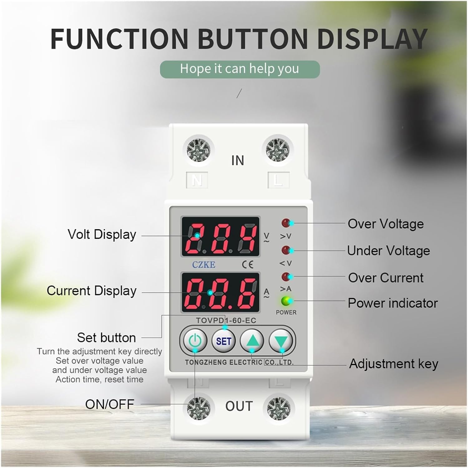
Figure 2: Front view of the CZKE TOVPD1-60-EC showing the dual LED display for voltage and current, along with indicator lights for over-voltage, under-voltage, over-current, and power. The control buttons (Set, Up, Down) are clearly visible for parameter adjustment.
- Volt Display: Shows real-time voltage.
- Current Display: Shows real-time current.
- Indicator Lights:
- >V: Over Voltage indicator.
- <V: Under Voltage indicator.
- >A: Over Current indicator.
- POWER: Power indicator.
- Set Button: Used to enter and confirm parameter settings.
- Up/Down Buttons: Used to navigate and adjust parameter values.
- ON/OFF Button: Manual control for power output.
4. Specifications
| Parameter | Value/Range |
|---|---|
| Model Number | TOVPD1-60-EC |
| Power Supply | 230VAC 50/60Hz |
| Max. Loading Power | 1~40A Adjustable (default: 40A) or 1~63A Adjustable (default: 63A) |
| Over-voltage Protection Value Range | 230V~300V~OFF (default: 270V) |
| Over-voltage Recovery Voltage Range | 225V--295V (default: 250V) |
| Over-voltage Protection Action Time | 0.1s~30s (default: 0.5s) |
| Over-voltage Recovery Delay Time | 1s~500s (default: 30s) |
| Under-voltage Protection Value Range | 140V--210V --OFF (default: 170V) |
| Under-voltage Recovery Voltage Range | 145V--215V (default: 190V) |
| Under-voltage Protection Action Time | 0.1s~30s (default: 0.5s) |
| Under-voltage Recovery Delay Time | 1s~500s (default: 30s) |
| Over-current Adjustment Range | 1-40A (default: 20A) or 1-63A (default: 40A) |
| Over-current Action Range | 0.1~30 seconds (default: 0.5s) |
| Over-current Recovery Delay Time | 1s~500s (default: 30s) |
| Power-on Delay Time | 1s~500s (default: 10s) |
| Power Consumption | <2W |
| Electrical Machinery Life | 100,000 times |
| Installation | 35mm DIN rail |
| Voltage Calibration (A13) | +/-10% adjustable |
| Current Limit Times (A14) | 1-20 times (default off) |
5. Installation
The CZKE TOVPD1-60-EC is designed for 35mm DIN rail mounting. Ensure all power is disconnected before proceeding with installation.
5.1. Mechanical Installation
- Locate a suitable 35mm DIN rail within your electrical panel.
- Align the device's DIN rail clip with the rail.
- Press the device firmly onto the DIN rail until it clicks into place, ensuring it is securely fastened.
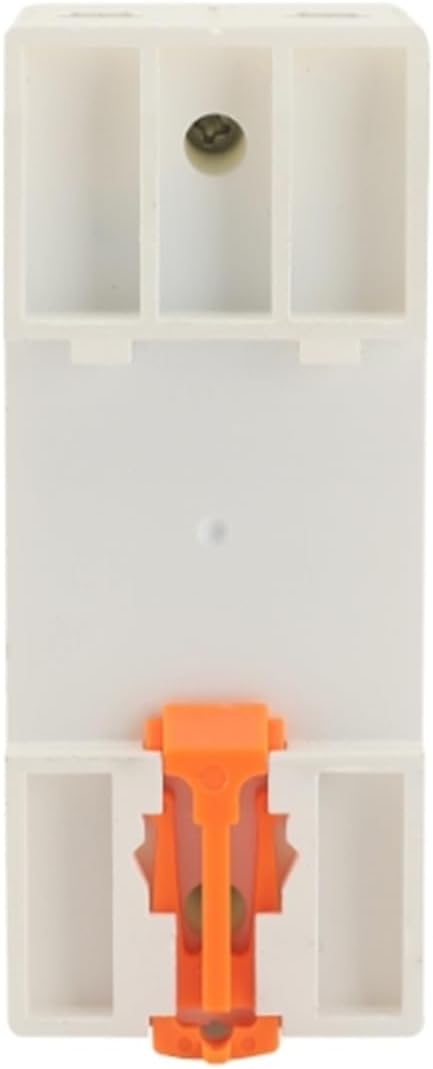
Figure 3: Rear view of the CZKE TOVPD1-60-EC, highlighting the integrated DIN rail mounting clip for quick and secure installation.
Video 1: This video demonstrates the physical installation of an adjustable voltage current protector onto a DIN rail, showing the sliding design for easy positioning and quick mounting.
5.2. Electrical Wiring
Connect the input and output wires as shown in the diagram below. Ensure all connections are tight and secure.

Figure 4: Angled view of the CZKE TOVPD1-60-EC, illustrating the input (IN) and output (OUT) terminals for neutral (N) and live (L) wires. This image helps visualize the wiring points.
- Connect the incoming neutral wire to the 'N IN' terminal.
- Connect the incoming live wire to the 'L IN' terminal.
- Connect the outgoing neutral wire to the 'N OUT' terminal.
- Connect the outgoing live wire to the 'L OUT' terminal.
- Double-check all connections for polarity and tightness.
6. Operating Instructions
6.1. Power On/Off
- After successful installation, apply power to the input terminals. The device will perform a self-test and display current voltage and current readings.
- Use the red ON/OFF button to manually switch the output power.
6.2. Parameter Settings
To enter the parameter setting mode, press and hold the 'SET' button for approximately 3-5 seconds until the display changes to 'P01'. Use the 'Up' and 'Down' buttons to navigate through the parameters (P01-P14) and adjust their values. Press 'SET' again to confirm a value and move to the next parameter, or to exit the setting mode after the last parameter.
Video 2: This video demonstrates how to adjust the various parameters (P01-P19) on the voltage and current protector, showing the button presses and display changes.
6.3. Fault Inquiry and Factory Reset
- Fault Inquiry: To view the last recorded fault events, press and hold the 'UP' button for more than 12 seconds. The device will display a history of up to 5 faults.
- Restore Factory Settings: To reset all parameters to their default values, press and hold the 'DOWN' button for more than 12 seconds. Use this function with caution as it will erase all custom settings.
7. Protection Functions
7.1. Over-Voltage Protection
When the detected voltage exceeds the set over-voltage protection value (P01), the device will instantly cut off the power supply to protect connected equipment. The '>V' indicator will illuminate. After the voltage returns to the normal range (P02) and the recovery delay time (P04) elapses, the device will automatically restore power.
Video 3: This video demonstrates the over-voltage protection feature, showing the device cutting power when voltage exceeds the set limit and automatically restoring it after recovery.
7.2. Under-Voltage Protection
If the voltage drops below the configured under-voltage protection value (P05), the device will disconnect the power output. The '<V' indicator will illuminate. Power will be restored automatically once the voltage stabilizes within the safe operating range (P06) and the recovery delay (P08) is complete.
Video 4: This video illustrates the under-voltage protection, demonstrating how the device cuts power when voltage drops too low and automatically restarts once voltage is stable.
7.3. Over-Current Protection
Should the current drawn by connected equipment exceed the set over-current adjustment range (P09), the protector will immediately cut off the power. The '>A' indicator will illuminate. Power will be restored after the over-current condition is resolved and the recovery delay (P11) has passed.
Video 5: This video showcases the over-current protection, demonstrating the device's response to excessive current draw and its automatic recovery feature.
7.4. Automatic Recovery and Delayed Start
The device features an automatic recovery function, which restores power once voltage and current conditions return to normal after a fault. Additionally, a configurable power-on delay (P12) prevents immediate power restoration, protecting sensitive equipment from sudden surges or rapid on/off cycles.
Video 6: This video highlights the automatic reset function and delayed start, showing how the device intelligently manages power restoration to prevent instant impact on connected loads.
8. Detailed Parameter Settings (P-Codes)
The following table details the adjustable parameters and their default values. Refer to section 6.2 for instructions on how to access and modify these settings.
| Parameter Code | Description | Default Value | Adjustable Range |
|---|---|---|---|
| P01 | Over-voltage protection value | 270V | 230V~300V~OFF |
| P02 | Over-voltage recovery voltage | 250V | 225V--295V |
| P03 | Over-voltage protection action time | 0.5s | 0.1s~30s |
| P04 | Over-voltage recovery delay time | 30s | 1s~500s |
| P05 | Under-voltage protection value | 170V | 140V--210V --OFF |
| P06 | Under-voltage recovery voltage | 190V | 145V--215V |
| P07 | Under-voltage protection action time | 0.5s | 0.1s~30s |
| P08 | Under-voltage recovery delay time | 30s | 1s~500s |
| P09 | Over-current adjustment range | 20A (for 40A model) / 40A (for 63A model) | 1-40A / 1-63A |
| P10 | Over-current action range | 0.5s | 0.1~30s |
| P11 | Over-current recovery delay time | 30s | 1s~500s |
| P12 | Power-on delay time | 10s | 1s~500s |
| P13 | Voltage calibration | 0% | +/-10% |
| P14 | Current limit times | OFF | 1-20 times (or OFF) |
9. Troubleshooting
| Problem | Possible Cause | Solution |
|---|---|---|
| Device does not power on. | No input power; incorrect wiring. | Check power supply; verify wiring connections. |
| Output power is off, '>V' indicator is on. | Over-voltage condition detected. | Check input voltage; device will auto-recover when voltage normal. |
| Output power is off, '<V' indicator is on. | Under-voltage condition detected. | Check input voltage; device will auto-recover when voltage normal. |
| Output power is off, '>A' indicator is on. | Over-current condition detected. | Reduce load or check for short circuits; device will auto-recover when current normal. |
| Cannot change settings. | Not in setting mode; buttons not pressed correctly. | Press and hold 'SET' button for 3-5 seconds to enter setting mode. |
| Device frequently trips. | Protection parameters set too sensitively; unstable power supply. | Adjust protection thresholds (P01, P05, P09) to appropriate levels; consult an electrician for power supply stability. |
For further assistance, please contact customer support.
10. Maintenance
- Regular Inspection: Periodically check the device for any signs of physical damage, loose connections, or overheating.
- Cleaning: Use a soft, dry cloth to clean the device. Do not use abrasive cleaners or solvents. Ensure power is off before cleaning.
- Firmware Updates: Check the manufacturer's website for any available firmware updates, though this device typically does not require user-level updates.
- Environmental Control: Maintain a stable environment, avoiding excessive dust, humidity, and temperature fluctuations.
11. Warranty and Support
This product comes with a standard manufacturer's warranty. Please refer to the warranty card included with your purchase for specific terms and conditions. For technical support, troubleshooting assistance, or warranty claims, please contact CZKE customer service through your retailer or the official CZKE website.
Contact Information:
- Visit the CZKE Store on Amazon for product information and support.
- Refer to your purchase documentation for direct manufacturer contact details.