Introduction
This manual provides detailed instructions for the installation, configuration, and operation of your Binardat CPE450 5.8GHz Outdoor Wireless Bridge. This device is designed to establish a stable and efficient wireless network connection over distances of 1-3 kilometers, suitable for various outdoor applications requiring reliable point-to-point or point-to-multipoint connectivity.
Product Overview
Key Features
- 5.8GHz Wireless Communication: Operates on the 5.8GHz frequency band, offering a transmission distance of 1-3KM with a maximum rate of 100Mbps.
- Two-Step Pairing: Simplifies setup with Master (M) and Slave (S) DIP switch settings and a channel synchronization button.
- Flexible Power Supply: Supports both 12V DC and Power over Ethernet (PoE) power supply.
- Bridge Connection: Facilitates network extension by connecting to upstream devices (Router, NVR, switch) and downstream devices (camera, AP, switch).
- LED Indicators & Web Management: Provides clear status display via Power, LAN, signal, and channel indicators. Offers comprehensive configuration and monitoring through a WEB GUI.
- PtP & PtMP Support: Designed for outdoor use with a waterproof rating, supporting both Point-to-Point and Point-to-Multipoint connections. Can also function as a standalone Wi-Fi access point.
Package Contents
- 2 x Binardat CPE450 Wireless Bridge Units
- 2 x 24V PoE Adapters
- Mounting Accessories
- Quick Start Guide (refer to this manual for detailed instructions)
Setup Instructions
Step 1: Device Configuration (Master/Slave Pairing)
To establish a wireless link between two CPE450 units, follow these steps for quick pairing:
- Power On: Connect both wireless bridge units to their respective 24V PoE adapters and plug them into a power source.
- Set DIP Switches: On the back of each bridge, locate the DIP switch. Set one bridge to 'M' (Master) and the other bridge to 'S' (Slave).
- Synchronize Channels: Short press the 'Dig SW/Reset' button on both the Master and Slave units. Continue pressing until the digital LED display on both units shows the same channel number. Once the channels match, the units will automatically attempt to pair. The 'SIG' indicator will light up upon successful pairing.

Description: This image illustrates the two-step pairing process. Step 1 shows how to set the DIP switch to 'M' for the Master bridge and 'S' for the Slave bridge. Step 2 demonstrates pressing the 'Dig SW/Reset' button to synchronize the digital tube display, indicating successful pairing when the values match.
Step 2: Physical Installation and Network Connection
After successful pairing, install the bridges in their desired outdoor locations, ensuring a clear line of sight between them for optimal performance. The transmission angle of the wireless bridge is 60° directional, so adjust the angle carefully, especially for point-to-multipoint setups.
- Master Bridge Connection: Connect the Ethernet port of the Master bridge (or the LAN port of its PoE adapter) to your upstream network device, such as a router, NVR, or switch.
- Slave Bridge Connection: Connect the Ethernet port of the Slave bridge (or the LAN port of its PoE adapter) to your downstream network devices, such as IP cameras, another access point, or a switch. Alternatively, devices can connect to the Wi-Fi SSID broadcast by the Slave bridge (if configured) to access the network through the bridge.
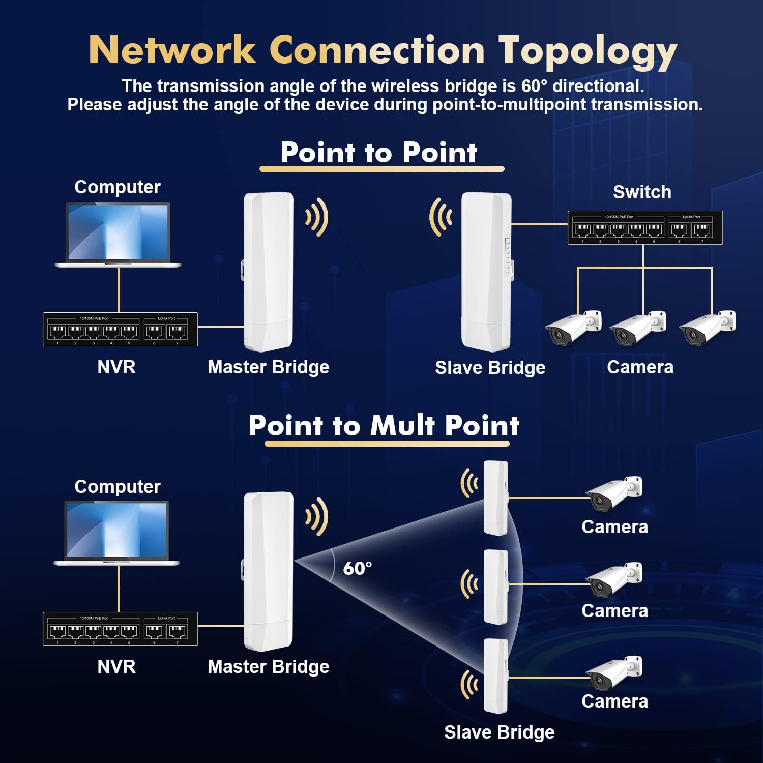
Description: This diagram shows two common network configurations. The top section illustrates a Point-to-Point setup connecting a computer/NVR to cameras/switch. The bottom section depicts a Point-to-Multipoint setup, where one Master bridge connects to multiple Slave bridges, each serving cameras. Note the 60-degree directional transmission angle.

Description: This image demonstrates the two methods of powering the wireless bridge units: using the included 24V Passive PoE adapter, which supplies power and data over a single Ethernet cable, or using a standard DC power adapter.
Operating Instructions
LED Indicators
The CPE450 units feature several LED indicators to provide real-time status information:
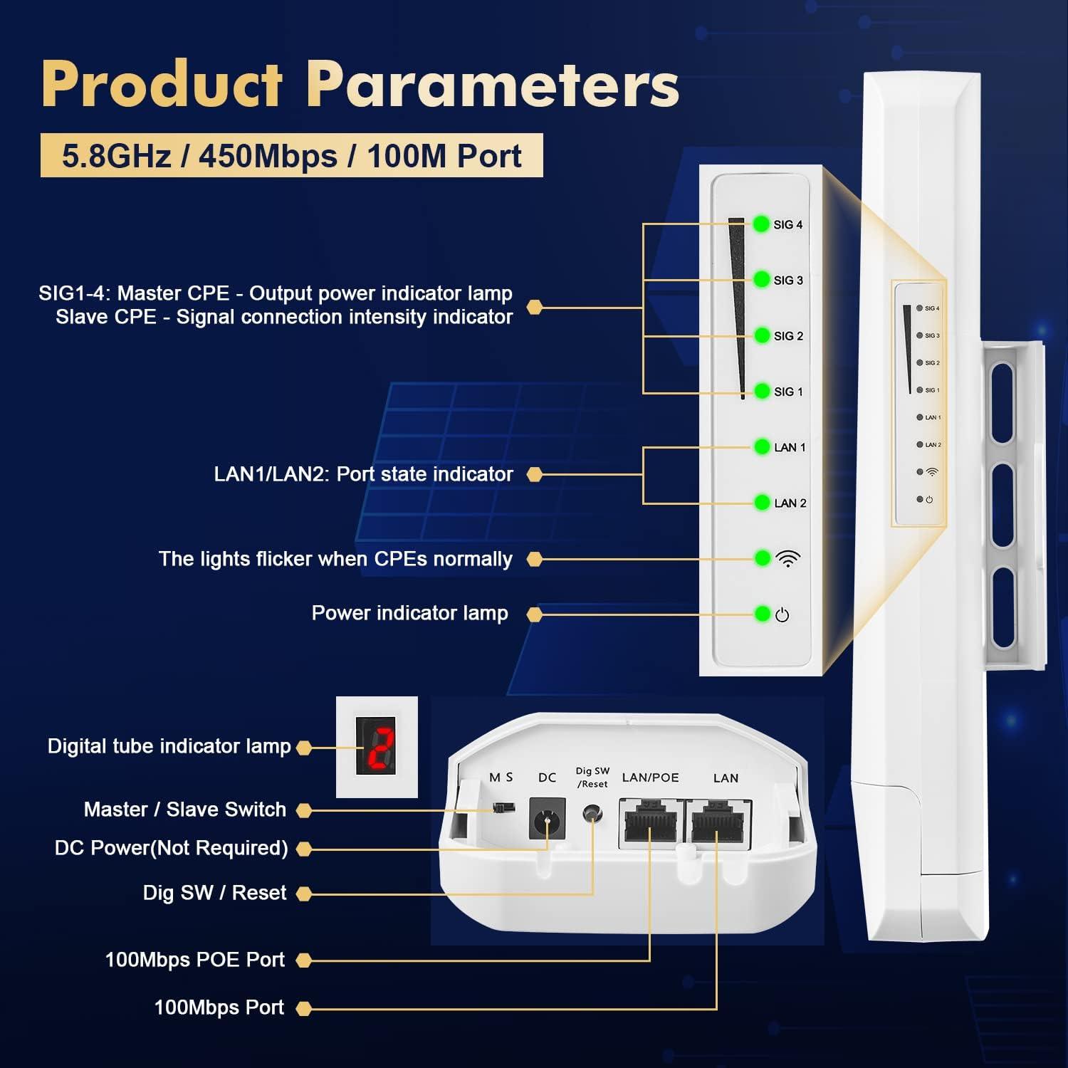
Description: This image provides a detailed breakdown of the CPE450's indicators and ports. It labels SIG1-4 as signal connection intensity indicators (or Master CPE output power indicator lamps), LAN1/LAN2 as port state indicators, and the power indicator lamp. It also shows the digital tube indicator, Master/Slave switch, DC power port, Dig SW/Reset button, and 100Mbps PoE and Ethernet ports.
- SIG 1-4: For Slave CPE, these indicate signal connection intensity. For Master CPE, they indicate output power. More lights mean a stronger signal/power.
- LAN 1/LAN 2: Indicate the status of the Ethernet ports. A solid light means a link is established, and flickering indicates data activity.
- Power Indicator: Illuminates when the device is powered on.
- Digital Tube Indicator: Displays the current channel number set for pairing.
Web Management Interface
The CPE450 supports management via a web-based graphical user interface (GUI). This allows for advanced configuration, status monitoring, and data statistics.
- Connect to the Device: Ensure your PC is connected to the same network segment as one of the bridge units (e.g., via an Ethernet cable to the LAN port of the PoE adapter).
- Access Web GUI: Open a web browser and enter the default management IP address: 192.254.254.254.
- Login: Use the default username admin and password admin to log in. It is highly recommended to change the default password after the initial setup for security purposes.
- Configuration: Within the web interface, you can view device status, set wireless parameters (e.g., SSID, encryption, password for standalone AP mode), and access data statistics. The default Wi-Fi SSID for standalone AP mode is 'Brap-2G-XXXX' or 'Brap-5G-XXXX' with a default password of 88888888.

Description: This image displays a laptop screen showing the web management interface of the wireless bridge. It highlights the default IP address (192.254.254.254), username (admin), and password (admin) for accessing the interface. The WiFi settings section is visible, allowing configuration of SSID and encryption.
Maintenance
To ensure the longevity and optimal performance of your Binardat CPE450 Wireless Bridge, consider the following maintenance guidelines:
- Environmental Protection: The device features an IP65 waterproof design, making it suitable for outdoor environments. However, ensure all cable connections are securely sealed to prevent moisture ingress.
- Clear Line of Sight: Regularly check that there are no new obstructions (e.g., growing foliage, new structures) blocking the line of sight between the Master and Slave units, as this can degrade signal quality.
- Firmware Updates: Periodically check the Binardat official website for any available firmware updates. Keeping the firmware updated can improve performance, stability, and security.
- Physical Inspection: Occasionally inspect the physical condition of the units and mounting hardware for any signs of wear, damage, or loose connections.

Description: This image emphasizes the robust design of the wireless bridge for outdoor use, showcasing its IP65 waterproof rating, resistance to frost and insolation, and a wide operating temperature range of -30°C to 50°C.
Troubleshooting
If you encounter issues with your Binardat CPE450 Wireless Bridge, refer to the following common problems and solutions:
- No Connection/Poor Signal:
- Ensure a clear line of sight between the Master and Slave units. Any physical obstructions can severely impact signal quality.
- Verify that both units are powered on and the power indicator LEDs are lit.
- Check the DIP switch settings (M for Master, S for Slave) and ensure the digital tube displays the same channel number on both units after pressing the 'Dig SW/Reset' button.
- Adjust the alignment of the units to optimize signal strength. Observe the SIG LEDs for improvement.
- Cannot Access Web Management Interface:
- Confirm your PC's IP address is in the same subnet as the bridge's default IP (192.254.254.x).
- Ensure your PC is directly connected to the bridge's LAN port or the LAN port of its PoE adapter.
- Try clearing your browser's cache or using a different browser.
- Verify the default IP address (192.254.254.254) is entered correctly.
- Network Devices Not Receiving Internet:
- Check all Ethernet cable connections for proper seating and integrity.
- Ensure the upstream router/NVR is functioning correctly and providing internet access.
- Verify the LAN LEDs on both bridge units are active, indicating a successful physical connection.
- Device Reset: If issues persist, you can perform a factory reset by pressing and holding the 'Dig SW/Reset' button for approximately 10 seconds until the LEDs flash, then release. This will revert all settings to their factory defaults.
Specifications
| Feature | Specification |
|---|---|
| Model Number | CPE450 |
| Brand | Binardat |
| Frequency Band Class | Single-Band (5.8 GHz Radio Frequency) |
| Wireless Communication Standard | 5.8 GHz Radio Frequency |
| Transmission Distance | 1-3 KM |
| Maximum Rate | 100Mbps |
| Ethernet Ports | 2 x 100Mbps Ethernet Ports |
| PoE Adapter | 24V Passive PoE Adapter (Included) |
| Power Supply | 12V DC or PoE |
| Antenna Type | Internal |
| Waterproof Rating | IP65 |
| Operating Temperature | -30°C to 50°C |
| Item Weight | 2.53 pounds (1.15 Kilograms) |
| Package Dimensions | 10.94 x 10.47 x 3.7 inches |
| Compatible Devices | Personal Computer, NVR, IP Cameras, Switches, Access Points |
Warranty and Support
Binardat products are designed for reliability and performance. For specific warranty information, please refer to the documentation included with your purchase or visit the official Binardat website. If you require technical assistance, troubleshooting support, or have questions regarding your CPE450 Wireless Bridge, please contact Binardat customer support through their official channels.
For the latest support resources and contact details, please visit the Binardat Store on Amazon or their official website.