Binardat CPE300
Binardat Outdoor Wireless Bridge User Manual
Model: CPE300
Introduction
The Binardat Outdoor Wireless Bridge (Model CPE300) is designed to extend Ethernet networks wirelessly over long distances, suitable for outdoor environments. This device operates on the 2.4GHz frequency band, offering a transmission distance of 500-1000 meters with a maximum rate of 100Mbps. It supports both Point-to-Point (PtP) and Point-to-Multi-Point (PtMP) connections, providing a reliable solution for various networking needs, including connecting security cameras, remote access points, or extending network coverage to distant buildings.
The package includes two bridge units, which can be configured as master and slave for easy pairing. Key features include IP65 waterproof rating, PoE power supply support, and web-based management for advanced configuration.

Image: Two Binardat Outdoor Wireless Bridge units, showing their compact, white design with indicator lights on the side.
Package Contents
Before proceeding with installation, please verify that all components are present in your package:
- 2 x Binardat Outdoor Wireless Bridge Units (Model CPE300)
- 2 x 24V PoE Adapters
- Mounting Accessories (e.g., straps, screws)
- User Manual (this document)

Image: The brown cardboard packaging box for the Binardat Outdoor Wireless Bridge, indicating the product name.
Setup and Installation
Power Supply Options
The Binardat Outdoor Wireless Bridge supports two power supply methods:
- 24V Passive PoE Powered: Connect the PoE adapter to the bridge unit using an Ethernet cable. This method allows for power and data transmission over a single cable, simplifying outdoor installations.
- DC Power Adapter Powered: The device can also be powered directly using a 12V DC power adapter (included).

Image: A diagram illustrating the two power supply modes: 24V Passive PoE powered via an Ethernet cable and direct power adapter powered.
Two-Step Pairing Process
The Binardat Wireless Bridge units are designed for quick and easy pairing without requiring complex login procedures. Follow these steps:
- Step 1: Set Master and Slave Units
Identify one bridge unit as the "Master" and the other as the "Slave." On each unit, locate the DIP switch (usually labeled M/S). Set the switch on the Master unit to 'M' and on the Slave unit to 'S'. Ensure both units are powered on.
- Step 2: Match Digital Tube Values
Short press the "Dig SW/Reset" button on both the Master and Slave units. Continue pressing until the value displayed on the LED screen (digital tube) of both units is the same. Once the values match, the units will automatically attempt to pair. The SIG indicator light will illuminate upon successful pairing.
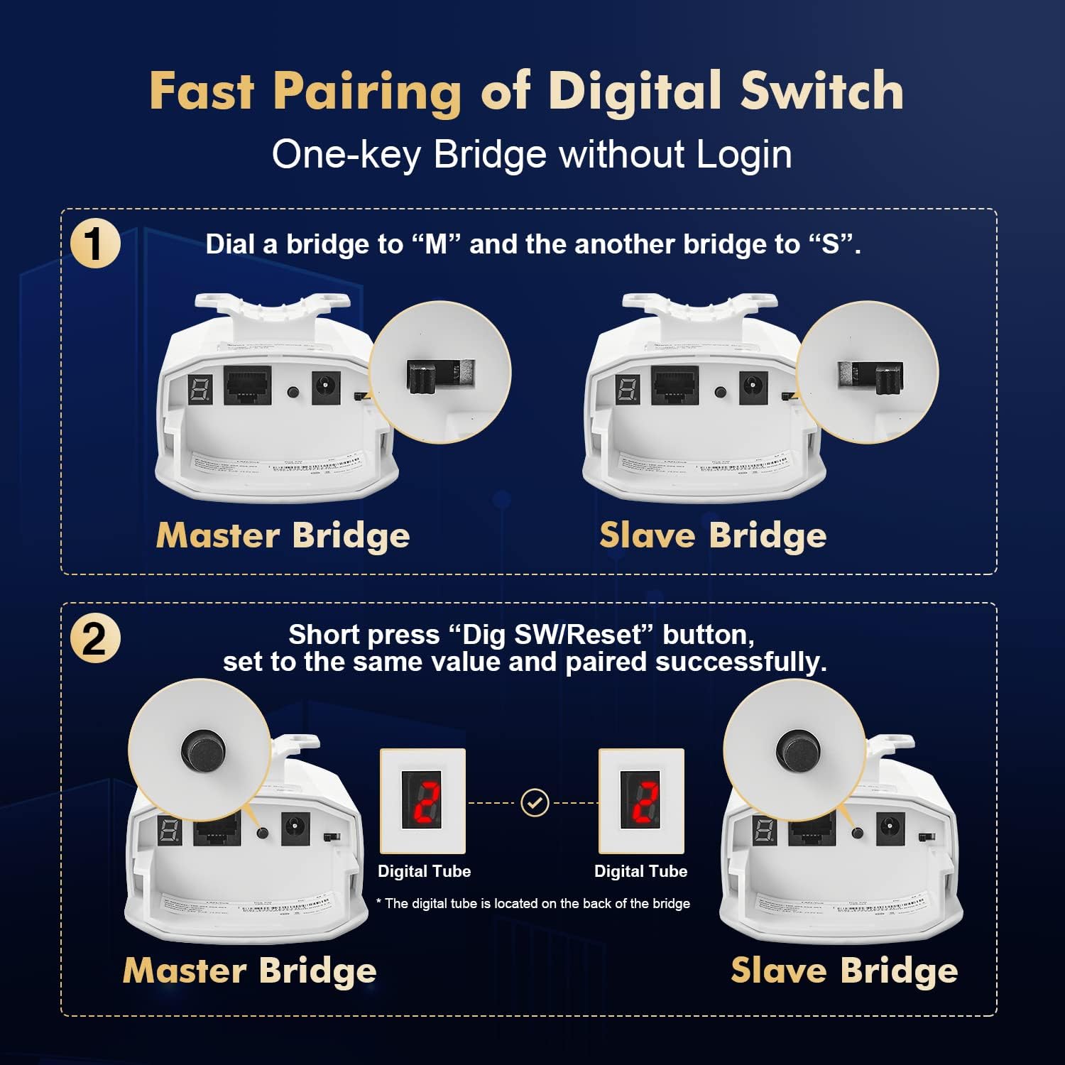
Image: A visual guide showing Step 1: setting the M/S DIP switch, and Step 2: pressing the Dig SW/Reset button to match the digital tube display for successful pairing.
For optimal performance, ensure a clear line of sight between the Master and Slave units. The transmission angle of the wireless bridge is 60° directional; adjust the angle during point-to-multipoint transmission for best results.
Operating Modes and Network Connection
Bridge Connection
Once paired, the wireless bridges facilitate network connectivity as follows:
- Connect the Ethernet port of the Master bridge (or the LAN port of its PoE adapter) to your upstream device, such as a router, NVR (Network Video Recorder), or network switch.
- Connect the Ethernet port of the Slave bridge (or the LAN port of its PoE adapter) to your downstream devices, such as IP cameras, access points (APs), or another network switch.
- Alternatively, devices can connect to the Wi-Fi SSID broadcast by the Slave bridge, allowing them to access the network through the established wireless link.
Point-to-Point (PtP) and Point-to-Multi-Point (PtMP)
The Binardat Wireless Bridge supports both common deployment scenarios:
- Point-to-Point (PtP): A direct wireless link between two locations, typically one Master unit and one Slave unit, to extend a single network segment.
- Point-to-Multi-Point (PtMP): A Master unit can connect wirelessly to multiple Slave units, allowing network extension to several remote locations from a central point. Remember to adjust the transmission angle (60° directional) for optimal coverage in PtMP setups.

Image: A diagram illustrating typical network connection topologies, including a Point-to-Point setup connecting two buildings and a Point-to-Multi-Point setup where one master unit connects to multiple slave units.
Web Management Interface
For advanced configuration, monitoring, and troubleshooting, the bridges can be managed via a web-based graphical user interface (GUI). To access the web interface:
- Connect your PC to the same network segment as the Master or Slave bridge.
- Open a web browser and enter the default management IP address: 169.254.254.254.
- Log in using the default credentials: Username: admin, Password: admin.
- From the web interface, you can view device status, configure wireless parameters (e.g., SSID, encryption), and access data statistics.

Image: A laptop screen displaying the web management interface for the wireless bridge, showing Wi-Fi settings and login details.
Maintenance and Environmental Considerations
The Binardat Outdoor Wireless Bridge is designed for durability and reliable operation in various outdoor conditions.
- IP65 Waterproof Design: The units feature an IP65 rating, providing protection against dust ingress and low-pressure water jets from any direction. This makes them suitable for outdoor installation in rain or snow.
- Temperature Tolerance: The devices are built to operate within a wide temperature range, typically from -30°C to 50°C, ensuring performance in diverse climates.
- Regular Inspection: Periodically inspect the physical condition of the units and mounting hardware, especially after severe weather events, to ensure secure attachment and integrity of cables.
- Clear Line of Sight: Maintain a clear line of sight between the bridges. Obstructions like dense foliage or new constructions can degrade signal quality. Trim vegetation as needed.

Image: An outdoor scene depicting the Binardat Wireless Bridge mounted on a building, with rain effects, emphasizing its IP65 waterproof, frost, and insulation features for outdoor environments.
Troubleshooting
This section provides solutions to common issues you might encounter.
LED Indicators Overview
Understanding the LED indicators on the device can help diagnose issues:
- PWR (Power): Indicates if the device is receiving power. Should be solid ON.
- LAN (Local Area Network): Indicates Ethernet port activity. Blinks when data is transmitted.
- SIG1-3 (Signal Strength): Indicates the strength of the wireless signal. More lights illuminated mean a stronger signal.
- Digital Tube: Displays the channel number during pairing and operation.

Image: A detailed view of the Binardat Wireless Bridge, highlighting its ports (100Mbps Ethernet, DC Power, Dig SW/Reset) and LED indicators (SIG1-3, LAN, PWR, Digital Tube).
Common Issues and Solutions
| Problem | Possible Cause | Solution |
|---|---|---|
| No Power (PWR LED OFF) | No power supply; faulty adapter/cable. | Check power connections. Ensure PoE adapter is correctly connected or DC adapter is plugged in. Try a different power outlet. |
| No Link (LAN LED OFF) | Ethernet cable issue; connected device off/faulty. | Verify Ethernet cable connection to the bridge and the connected device. Try a different Ethernet cable. Ensure the connected device is powered on and functioning. |
| No Wireless Connection (SIG LEDs OFF/Low) | Units not paired; poor line of sight; interference. | Re-perform the two-step pairing process. Ensure clear line of sight between units. Adjust alignment. Check for physical obstructions. |
| Slow Speed/Intermittent Connection | Weak signal; interference; excessive distance. | Check SIG LEDs for signal strength. Improve line of sight. Reduce distance if possible. Avoid placing near strong interference sources (e.g., large metal objects, other 2.4GHz devices). |
| Cannot Access Web Management | Incorrect IP/credentials; network configuration. | Ensure your PC's IP address is in the same subnet as the bridge (e.g., 169.254.x.x). Verify the default IP (169.254.254.254) and credentials (admin/admin). Temporarily disable PC firewall. |
If issues persist, consider performing a factory reset by pressing and holding the "Dig SW/Reset" button for approximately 10 seconds until the LEDs flash. This will revert all settings to default.
Specifications
| Feature | Detail |
|---|---|
| Model Number | CPE300 |
| Brand | Binardat |
| Frequency Band | 2.4 GHz Radio Frequency (Single-Band) |
| Max Transmission Rate | 100 Mbps |
| Transmission Distance | 500M-1KM (0.5 - 1 kilometer) |
| Ethernet Ports | 2 x 100Mbps Ethernet Ports |
| Power Supply | 24V Passive PoE / 12V DC |
| Waterproof Rating | IP65 |
| Operating Temperature | -30°C to 50°C |
| Antenna Type | Internal |
| Item Weight | 1.54 pounds |
| Package Dimensions | 7.87 x 5.91 x 3.94 inches |
Warranty and Support
Binardat products are designed for reliability and performance. For detailed warranty information, please refer to the warranty card included with your product or visit the official Binardat website.
For technical support, troubleshooting assistance, or further inquiries, please contact Binardat customer service. You may also refer to the official User Guide PDF available online for more comprehensive details:
Manufacturer: Binardat
Ask a question about this manual
Ask about setup, troubleshooting, compatibility, parts, safety, or missing instructions. Manuals+ will review the question and use this page’s manual context to help answer it.