1. Introduction
This manual provides essential information for the proper use and handling of the Bridgold MMBT3904 (NPN) and MMBT3906 (PNP) SMD General Purpose Amplifier Transistors. These transistors are designed for low power surface mount applications and are housed in the SOT-23 package. This kit includes 50 pieces of MMBT3904 and 50 pieces of MMBT3906.
2. Product Overview
The MMBT3904 and MMBT3906 are complementary NPN and PNP transistors, respectively, suitable for general-purpose amplification. They offer reliable performance in various electronic circuits.
- MMBT3904: NPN General Purpose Amplifier Transistor
- MMBT3906: PNP General Purpose Amplifier Transistor (complementary to MMBT3904)
- Package Type: SOT-23 Surface Mount
- Power Dissipation: Capable of 350mW
- Moisture Sensitivity Level: 1

Figure 1: Top view of MMBT3904 (1AM marking) and MMBT3906 (2A marking) SOT-23 transistors. The image shows two small black rectangular components with three metal leads each, indicating their surface-mount design.

Figure 2: Bottom view of MMBT3904 and MMBT3906 SOT-23 transistors, showing the solder pads. The image displays the underside of the two transistors, highlighting the three metallic pads designed for surface mounting onto a circuit board.
3. Setup and Installation
These transistors are designed for surface mount technology (SMT) applications. Proper handling and soldering techniques are crucial for reliable operation.
- Component Identification:
Identify the MMBT3904 (NPN) and MMBT3906 (PNP) transistors. MMBT3904 typically has a "1AM" marking, while MMBT3906 has a "2A" marking on the package. Refer to Figure 1 for visual identification.

Figure 3: Close-up view of MMBT3904 (marked '1AM') and MMBT3906 (marked '2A') transistors, showing their distinct package markings for identification. This image provides a clearer view of the text printed on the top surface of each transistor.
- Pin Configuration (SOT-23):
The SOT-23 package has three pins: Base (B), Emitter (E), and Collector (C). The exact pinout depends on the manufacturer and specific part. Always refer to the datasheet for the precise pin configuration for your application. A common pinout for SOT-23 transistors is shown in Figure 5 (Dimensions and Pinout).
- Soldering:
Use appropriate SMT soldering techniques (e.g., reflow soldering or fine-tip soldering iron) to attach the transistors to the printed circuit board (PCB). Ensure proper alignment and avoid excessive heat, which can damage the component.
- Recommended soldering temperature and time should adhere to industry standards for SOT-23 packages.
- Ensure solder joints are clean and free of bridges.
- Environmental Considerations:
Store and handle transistors in an environment with controlled moisture and static electricity to prevent damage. These components have a Moisture Sensitivity Level 1.
4. Operating Guidelines
These transistors are designed for general-purpose amplifier applications. Adhere to the electrical characteristics and absolute maximum ratings to ensure optimal performance and longevity.
- Voltage and Current Limits: Do not exceed the maximum voltage and current ratings specified in the electrical characteristics table (see Section 6).
- Power Dissipation: The maximum power dissipation is 350mW. Ensure adequate thermal management in your circuit design to prevent overheating.
- Circuit Design: Integrate these transistors into circuits designed for their NPN/PNP characteristics. MMBT3904 (NPN) is typically used for switching or amplification where the collector current flows from collector to emitter, while MMBT3906 (PNP) is used where current flows from emitter to collector.
5. Maintenance and Handling
These transistors are passive components and generally require no maintenance once installed. However, proper handling is essential.
- Storage: Store unused transistors in their original packaging or in anti-static bags in a dry, cool environment.
- Static Electricity: Always use anti-static precautions (e.g., ESD wrist straps, grounded work surfaces) when handling these components to prevent damage from electrostatic discharge.
- Cleaning: If cleaning is necessary, use isopropyl alcohol and a soft brush. Avoid harsh chemicals or abrasive materials.
6. Specifications and Electrical Characteristics
The following tables provide detailed electrical characteristics and package dimensions for the MMBT3904 and MMBT3906 transistors.
6.1. Electrical Characteristics (TA=25°C unless otherwise specified)
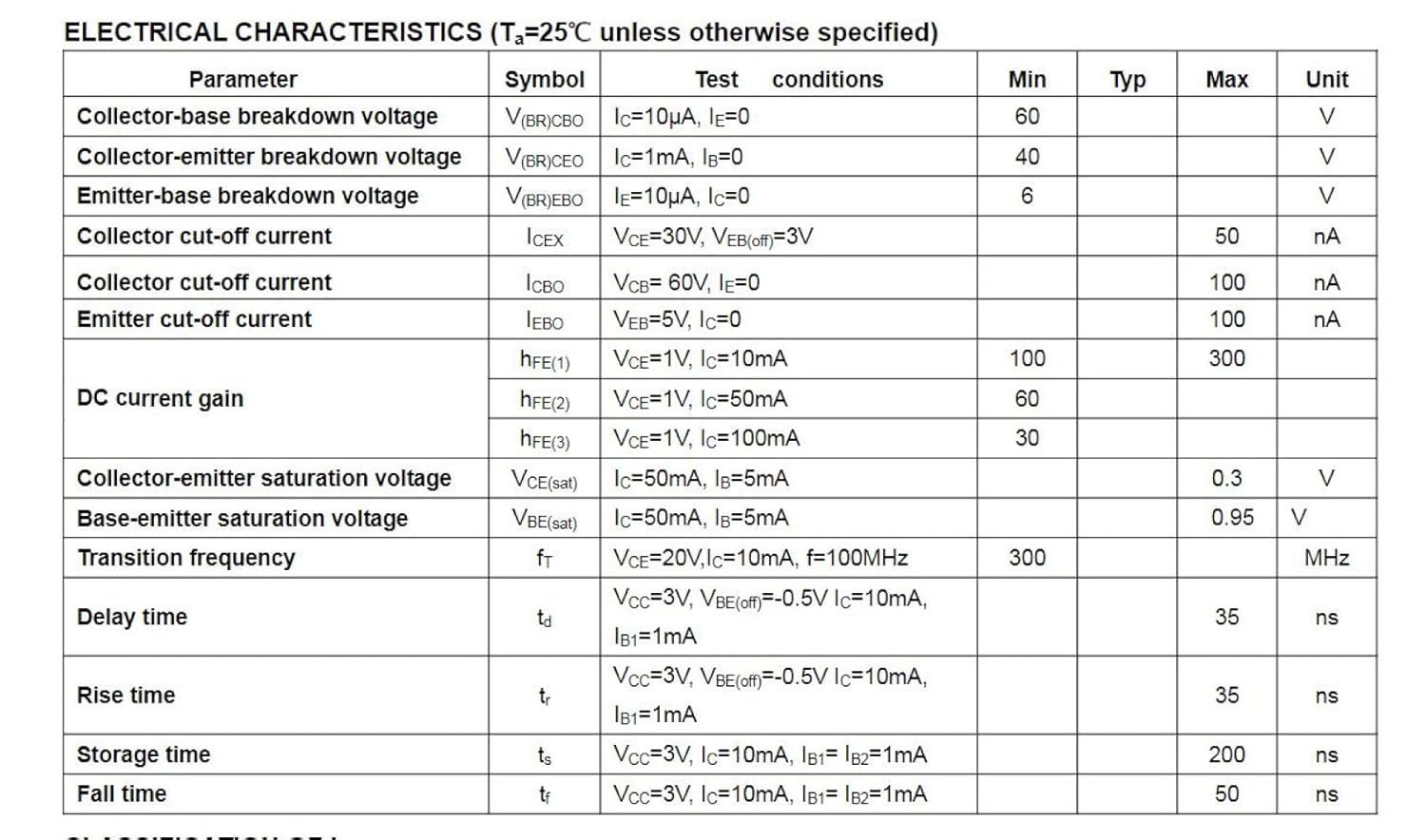
Figure 4: Table detailing the electrical characteristics of the transistors, including breakdown voltages, collector cut-off current, DC current gain (hFE), saturation voltages, transition frequency, and switching times (delay, rise, storage, fall). This table provides critical performance parameters for circuit design.
Note: Exposure to absolute maximum rating conditions for extended periods may affect device reliability.
6.2. Package Dimensions (SOT-23)

Figure 5: Diagram illustrating the SOT-23 package dimensions with corresponding measurements in millimeters and inches. This includes top, side, and end views of the package, along with a table specifying minimum and maximum values for each dimension (A, A1, A2, b, c, D, E, E1, e, e1, L, L1, θ).
Item Model Number: bg-216
Package Dimensions: 5.24 x 3.23 x 0.67 inches; 0.63 ounces (for the entire kit)
7. Troubleshooting
If you encounter issues with the transistors, consider the following common troubleshooting steps:
- No Output/Incorrect Behavior:
- Verify correct pin orientation (Base, Emitter, Collector) according to the datasheet.
- Check for cold solder joints or solder bridges.
- Ensure the correct transistor type (NPN/PNP) is used for the circuit design.
- Confirm that the operating voltages and currents are within the specified limits.
- Overheating:
- Check if the power dissipation exceeds 350mW.
- Ensure proper thermal management in the PCB layout.
- Verify that the load impedance is appropriate.
- Component Damage:
- Inspect for physical damage or discoloration due to excessive heat during soldering or operation.
- Test the component with a multimeter for shorts or open circuits if suspected damage.
8. Support Information
For further technical assistance or inquiries, please contact Bridgold customer support through their official channels. Refer to the product packaging or the point of purchase for specific contact details.
Manufacturer: Bridgold
Date First Available: June 11, 2022