Introduction
This manual provides detailed instructions for the installation, operation, and maintenance of your KAOLALI GPS Speedometer. This device is designed for accurate speed measurement and display in various vehicles, including marine vessels, cars, trucks, and motorcycles.
Product Features
- Constructed from high-quality 316 stainless steel, ABS, and PC materials for durability.
- IP67 waterproof rating ensures reliable performance in marine and outdoor environments.
- Displays current speed (Speed Over Ground - SOG), odometer (ODO), trip meter (TRIP), Course Over Ground (COG), and battery voltage.
- Adjustable odometer (can be reset via the back button).
- Supports multiple speed units: Knots, MPH, and Km/h, switchable via a back button.
- Wide operating voltage range: 9-32V DC.
- Features a TFT screen for clear display.
Package Contents
Upon opening the package, verify that all components are present and undamaged:
- 1x KAOLALI GPS Speedometer
- 1x GPS Antenna
- 1x Multi-plug socket
- 1x Instruction Manual (this document)
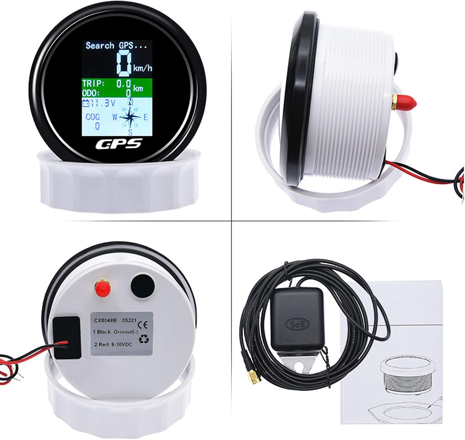
Figure 1: Package Contents. The image displays the main speedometer unit, the GPS antenna with its cable, a multi-plug socket, and the instruction manual.
Specifications
| Specification | Value |
|---|---|
| GPS SOG (Speed Over Ground) Range | 0-600 km/h |
| ODO (Odometer) Range | 0-999999 km (adjustable) |
| TRIP (Trip Meter) Range | 0-999.9 km (resets when power is off) |
| COG (Course Over Ground) | Orientation Pointer |
| Battery Voltage | 9-32V DC |
| Switchable Units | Knots, MPH, Km/h |
| Degree of Protection | IP67 (Waterproof) |
| Backlight | TFT Screen |
| Diameter | 85mm (3-3/8") |
| Depth | 55mm (2-3/4") |
| Material | 316 Stainless Steel, ABS, PC |

Figure 2: Product Dimensions. The image illustrates the front and back views of the speedometer with key measurements: 96.7mm front diameter and 53.5mm depth.
Installation Guide
Proper installation is crucial for the optimal performance and longevity of your GPS speedometer. It is recommended that installation be performed by a qualified professional.
- Choose a Mounting Location: Select a flat, stable surface on your dashboard or panel that allows for clear visibility and easy access to the back of the unit for wiring. Ensure there is sufficient depth (at least 55mm) behind the panel for the gauge body.
- Cut the Mounting Hole: Using an 85mm (3-3/8 inch) hole saw, carefully cut a circular hole in the chosen mounting location.
- Connect Wiring:
- Connect the black wire to a reliable ground source (negative terminal of the battery or chassis ground).
- Connect the red wire to a switched 9-32V DC power source (positive terminal of the battery or an ignition-switched circuit).
- Connect the GPS antenna cable to the designated port on the back of the speedometer.
- Mount the Speedometer: Insert the speedometer into the cut hole. Secure it using the provided mounting ring and nuts from the back of the panel. Ensure a snug fit to maintain the IP67 seal.
- Position the GPS Antenna: Mount the GPS antenna in a location with a clear, unobstructed view of the sky. Avoid placing it under metal objects or near strong electromagnetic interference sources.

Figure 3: Example Installation. The speedometer is shown integrated into a vehicle's dashboard, demonstrating a typical mounting scenario.
Operating Instructions
Once installed and powered on, the speedometer will begin searching for a GPS signal. This may take a few moments, especially during the first use or if the unit has been moved a significant distance.
Display Overview

Figure 4: Display Features. This image highlights the various data points displayed on the speedometer screen, including Speed Over Ground (SOG), Trip Meter (TRIP), Odometer (ODO), Battery Voltage, and Course Over Ground (COG) with an orientation pointer.
- GPS SOG (Speed Over Ground): Displays your current speed.
- TRIP: Shows the distance traveled for the current trip. This value resets when the power is turned off.
- ODO (Odometer): Accumulates total distance traveled. This value can be adjusted/reset using the back button.
- Battery Voltage: Indicates the current voltage of your vehicle's battery (9-32V DC).
- COG (Course Over Ground): Provides an orientation pointer indicating your current direction of travel.
Switching Speed Units
To switch between speed units (Knots, MPH, Km/h), press the button located on the back of the unit. Each press will cycle through the available units.
Video 1: Unit Switching Demonstration. This video demonstrates how to cycle through the different speed units (Km/h, Knots, MPH) by pressing the button on the back of the speedometer. It also shows the waterproof capability of the device.
Maintenance
The KAOLALI GPS Speedometer is designed for durability and requires minimal maintenance. Follow these guidelines to ensure its longevity:
- Cleaning: Wipe the display and housing with a soft, damp cloth. Avoid using abrasive cleaners or solvents that could damage the surface.
- Connections: Periodically check all wiring connections to ensure they are secure and free from corrosion.
- Waterproof Seal: While the unit is IP67 waterproof, ensure the mounting is secure and the back cover (if removable) is properly sealed to maintain water resistance.

Figure 5: Waterproof Capability. The image shows the speedometer being subjected to water, highlighting its IP67 waterproof design suitable for marine and outdoor use.
Troubleshooting
If you encounter issues with your GPS speedometer, refer to the following common problems and solutions:
- "No GPS Signal" Displayed:
- Ensure the GPS antenna is properly connected to the unit.
- Verify the GPS antenna has a clear, unobstructed view of the sky. Relocate the antenna if necessary.
- Allow sufficient time (up to several minutes) for the unit to acquire a signal, especially after initial power-up or relocation.
- Inaccurate Speed Reading:
- Ensure the GPS antenna is securely mounted and not moving excessively.
- Confirm the unit is receiving a strong GPS signal.
- Speed accuracy can be affected by environmental factors or satellite availability.
- Display Not Lighting Up:
- Check all power connections (red wire for positive, black wire for ground) to ensure they are secure and receiving adequate voltage (9-32V DC).
- Verify the fuse in the power circuit (if applicable) is intact.
Warranty and Support
For warranty information, technical support, or further assistance, please refer to the official KAOLALI website or contact their customer service directly. A digital version of this user manual may also be available for download on the product's Amazon listing page under the "Product guides and documents" section.
You can find additional support and product information by visiting the KAOLALI Store on Amazon.