1. Introduction
This GoolRC Wireless Tire Pressure Monitoring System (TPMS) is designed to enhance riding safety by continuously monitoring the tire pressure and temperature of your motorcycle, e-bike, or bicycle. This manual provides essential information for proper installation, operation, and maintenance of your device. Please read it thoroughly before use.
2. Product Overview
2.1 Package Contents
- 1 x TPMS Display Unit
- 2 x External Tire Pressure Sensors
- 1 x USB Charging Cable
- 1 x Mounting Bracket
- 1 x Screw
- 1 x Wrench (for anti-theft sensor installation)
2.2 Key Features
- Real-time monitoring of tire pressure and temperature.
- Warning function with visual alerts for high/low pressure, high temperature, and low sensor battery.
- Three-digit precise digital display.
- Waterproof, dustproof, and high-temperature resistant design.
- Compact size for easy portability and installation.
- Automatic start/stop with vehicle movement to save battery.
- Magnetic charging for the display unit.
- 24-hour monitoring capability.

Figure 1: All Safety Functions Provided
This image illustrates the comprehensive safety features of the TPMS, including abnormal alarm, temperature monitoring, data update, wireless transmitter, stable signal, intelligent IC, digital display, 24H monitoring, and magnetic charging plug.

Figure 2: Display Unit Design
The display unit features a classic black design with a streamlined 'shark fin' shape, ensuring good appearance without affecting signal reception.
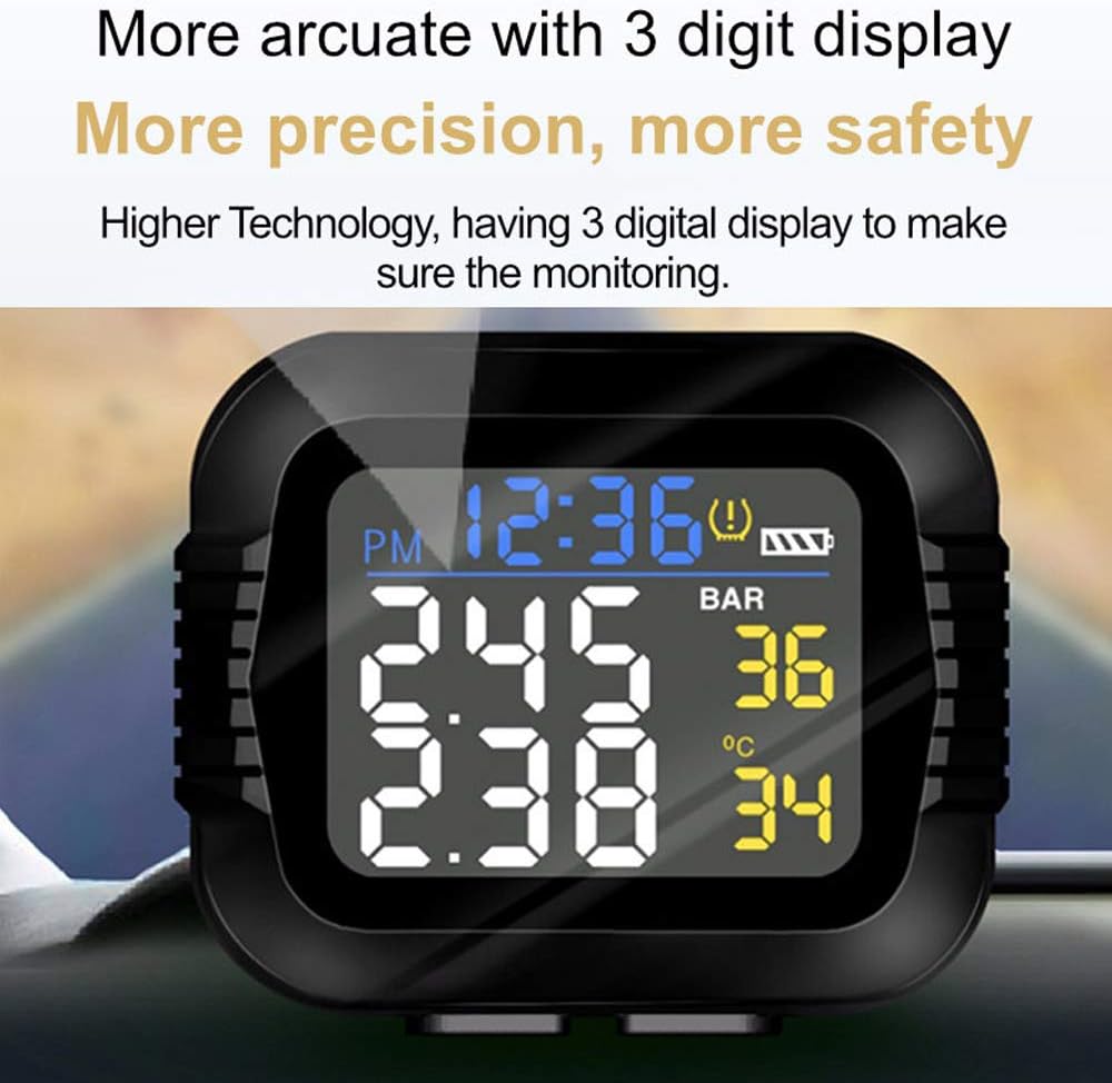
Figure 3: Arcuate 3-Digit Display
The display provides clear, precise 3-digit readings for enhanced monitoring accuracy and safety.
3. Setup
3.1 Charging the Display Unit
- Connect the provided USB charging cable to the magnetic charging port on the display unit.
- Plug the other end of the USB cable into a standard USB power adapter (not included) or a USB port.
- Charge the unit until the battery indicator shows full. Initial charging may take approximately one hour.
3.2 Installing the Display Unit
- Attach the mounting bracket to your motorcycle's handlebar or a suitable flat surface using the provided screw. Ensure it is securely fastened and does not obstruct your view or controls.
- Slide the TPMS display unit onto the mounting bracket until it clicks into place.
- Adjust the viewing angle for optimal visibility.
3.3 Installing the Sensors
- Identify the front (F) and rear (R) sensors. Each sensor is typically marked.
- Unscrew the original valve cap from your tire valve.
- Screw the corresponding sensor onto the tire valve stem. Tighten it firmly by hand.
- Use the provided wrench to further tighten the sensor's anti-theft nut (if applicable) to prevent accidental loosening or theft.
- Repeat for the other tire.
3.4 Initial Pairing and Settings
The sensors are usually pre-paired with the display unit. If they do not connect automatically, or if you replace a sensor, you may need to manually pair them. Refer to the specific instructions in the display unit's menu for sensor pairing. It is recommended to move the vehicle slightly after installation to activate the sensors and allow them to transmit data.
Setting the clock and pressure/temperature alarm thresholds can be complex. Follow the on-screen prompts and refer to the detailed instructions provided in the display unit's menu for accurate configuration. Ensure alarm thresholds are set appropriately for your vehicle's recommended tire pressure.
4. Operating Instructions
4.1 Power On/Off
The display unit will automatically power on when it detects vehicle movement and power off after a period of inactivity to conserve battery.

Figure 4: Automatic Start/Stop Function
The display unit automatically starts working when the motorcycle begins moving and powers off without operation, saving battery life.
4.2 Understanding the Display
The display shows real-time data for both front and rear tires. Key indicators include:
- Time Display: Current time.
- Battery Display: Indicates the display unit's battery level.
- Pressure Readings: Shows tire pressure in Bar or PSI (unit can be configured).
- Temperature Readings: Shows tire temperature in °C or °F (unit can be configured).
- Warning Symbol: An exclamation mark or specific icon indicates an alert condition.

Figure 5: Easy-to-Read Display
The display clearly shows front tire pressure (e.g., 2.45 Bar) and front tire temperature (e.g., 36 °C), along with time and battery status.
4.3 Warning Indicators
The system provides visual and audible warnings for abnormal conditions:
- High Pressure Warning: Displayed value turns red, and an alarm symbol appears.
- Low Pressure Warning: Displayed value turns red, and an alarm symbol appears.
- High Temperature Warning: Displayed value turns red, and an alarm symbol appears.
- Low Power Warning: Battery symbol indicates low power for either the display unit or a sensor.

Figure 6: Warning Diagram
This diagram illustrates how the display indicates various warning conditions: high pressure, low pressure, high temperature, and low power. The red part signifies the alarm symbol.
5. Maintenance
5.1 Sensor Battery Replacement
The external sensors use CR1632 batteries. When a sensor's battery is low, the display unit will show a low power warning. To replace:
- Unscrew the sensor from the tire valve.
- Carefully open the sensor casing (refer to the sensor's specific design for opening mechanism).
- Remove the old CR1632 battery and insert a new one, ensuring correct polarity.
- Close the sensor casing securely and re-install it on the tire valve.
5.2 Display Unit Charging
Recharge the display unit using the provided USB cable when the battery indicator shows low power. A full charge ensures continuous operation.
5.3 Cleaning
Wipe the display unit and sensors with a soft, damp cloth. Do not use abrasive cleaners or solvents. The unit is designed to be waterproof and dustproof, but avoid prolonged submersion.

Figure 7: Protection Design
The TPMS unit features a robust design, making it waterproof, dustproof, stable, and resistant to high temperatures, ensuring reliable performance in various weather conditions.
6. Troubleshooting
- Sensors Not Connecting/Displaying Readings:
Ensure sensors are correctly installed and tightened. Move the vehicle for a short distance to activate the sensors and allow them to transmit data. Check if the sensor batteries are charged. If issues persist, try re-pairing the sensors through the display unit's settings menu. - Inaccurate Readings:
Tire pressure readings may appear inconsistent when the vehicle is stationary. Readings become accurate once the vehicle is in motion and sensors are actively transmitting. Compare readings with a reliable manual gauge if you suspect significant discrepancies. - Display Not Turning On:
Ensure the display unit is fully charged. If it's charged but not turning on, try pressing and holding the power button (if available) or initiating vehicle movement to trigger auto-power on. - Persistent Alarms:
Check your tire pressure and temperature against recommended values. Verify that the alarm thresholds in the display unit's settings are correctly configured for your vehicle. Adjust tire pressure as needed. - Difficulty with Settings (Time, Units, Thresholds):
The setting interface can be non-intuitive. Refer to the detailed instructions within the display unit's menu or the manufacturer's online resources for step-by-step guidance. Patience and careful attention to the prompts are key.
7. Specifications
| Model Number | CJB2750258682703NC |
| Operating Temperature Range | -40 ℃ ~ +105 ℃ |
| Humidity | 100% |
| Sensor Battery Type | CR1632 (3V, 150mAh) |
| Sensor Standby Current | 1 μA |
| Sensor Operating Current | 15 mA |
| Pressure Range | 0 ~ 116 psi (0 ~ 8 Bar) |
| Temperature Range | -40 ℃ ~ +120 ℃ |
| Frequency | FSK433.92MHz |
| Package Dimensions | 115 x 75 x 70 mm (4.5 x 3.0 x 2.8 inches) |
| Package Weight | 243.5 g |
8. Warranty and Support
For technical assistance, warranty claims, or any product-related inquiries, please contact GoolRC customer service through the retailer where you purchased the product or visit the official GoolRC website for support contact information. Please retain your proof of purchase for warranty purposes.