1. Introduction
The Taidacent PWM Signal Amplifier Module YF-44 is designed to amplify the voltage and current of a weak Pulse Width Modulation (PWM) signal. This module is primarily intended for high-frequency applications, enabling control of higher power equipment such as motors, light bulbs, LED strips, DC motors, and micro water pumps.
It operates by amplifying the square wave width from its power supply, which ranges from 5V to 27V DC. The module utilizes a MOS tube chip for current driving, providing a current capability of up to 2A.
2. Product Overview
The module features clearly labeled input and output terminals for easy connection. It is a compact circuit board designed for integration into various electronic projects.
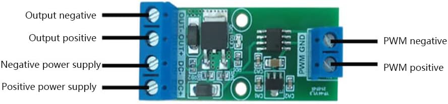
Figure 2.1: Top view of the Taidacent PWM Signal Amplifier Module YF-44, showing the green PCB with blue screw terminals for connections.
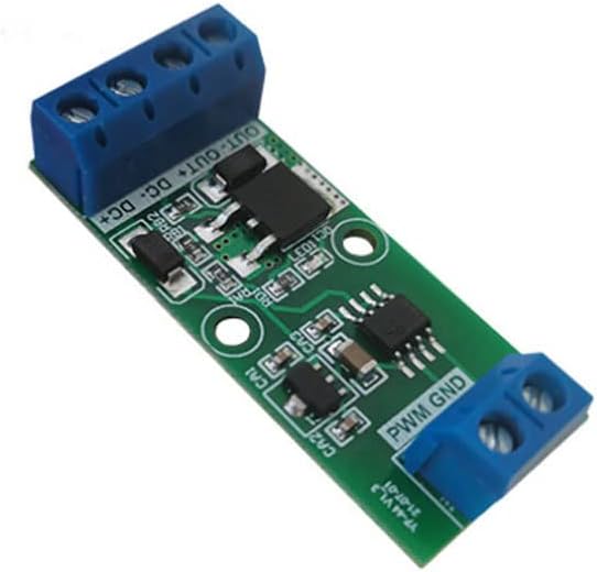
Figure 2.2: Angled view of the Taidacent PWM Signal Amplifier Module YF-44, highlighting the components and screw terminals.
3. Specifications
| Parameter | Value |
|---|---|
| Input Voltage (Power Supply) | DC 5V - 27V |
| Input Current (Power Supply) | 2A (Maximum) |
| Signal Voltage (PWM Input) | 3V - 5V |
| PWM Frequency Range | 0 - 10KHz |
| Output Current Capability | Up to 2A |
| Dimensions (L x W x H) | 1.96 x 0.81 x 0.07 inches (approx. 50 x 20.5 x 1.8 mm) |
| Model Number | YF-44 |

Figure 3.1: Image showing the PWM signal amplification module alongside its key specifications and an oscilloscope displaying a square wave signal.
4. Setup and Wiring
Proper wiring is crucial for the correct operation of the PWM signal amplifier module. Refer to the diagram below for connection details.

Figure 4.1: Wiring diagram illustrating connections for the PWM signal amplifier module.
4.1 Terminal Connections
- DC+ (Positive Power Supply): Connect the positive terminal of your DC 5V-27V power supply here.
- DC- (Negative Power Supply): Connect the negative terminal of your DC 5V-27V power supply here.
- PWM+ (PWM Positive Input): Connect the positive terminal of your PWM signal generator (3V-5V signal voltage) here.
- PWM- (PWM Negative Input / GND): Connect the negative terminal (ground) of your PWM signal generator here.
- OUT+ (Output Positive): Connect the positive terminal of the load (e.g., motor, LED strip) to be controlled.
- OUT- (Output Negative): Connect the negative terminal of the load to be controlled.
4.2 Connection Procedure
- Ensure all power sources are disconnected before making any connections.
- Connect the DC 5V-27V power supply to the DC+ and DC- terminals. Observe polarity.
- Connect your PWM signal generator to the PWM+ and PWM- terminals. Ensure the signal voltage is between 3V and 5V.
- Connect your load (e.g., motor, LED strip) to the OUT+ and OUT- terminals. Ensure the load's current requirement does not exceed 2A.
- Double-check all connections for correctness and secure fastening.
5. Operating Instructions
Once the module is correctly wired, follow these steps to operate it:
- Apply power to the DC+ and DC- terminals. The module should now be powered.
- Activate your PWM signal generator. The module will amplify this signal and apply it to the connected load.
- Adjust the frequency and duty cycle of your PWM signal generator as required for your application. The module will pass through and amplify these characteristics to the output.
- Monitor the behavior of your connected load to ensure it is functioning as expected.
The module's output current capability is up to 2A, allowing it to drive various devices that require higher current than the original PWM signal source can provide.
6. Maintenance
The Taidacent PWM Signal Amplifier Module YF-44 is a low-maintenance device. To ensure its longevity and reliable operation, consider the following:
- Keep Clean: Periodically clean the module with a soft, dry brush to remove dust and debris. Avoid using liquids.
- Environmental Conditions: Operate the module within a dry environment, away from excessive moisture, extreme temperatures, and corrosive substances.
- Physical Protection: Avoid physical shock or excessive force on the module, especially on the terminals and components.
- Power Off Before Handling: Always disconnect power before handling or making any changes to the wiring.
7. Troubleshooting
If you encounter issues with the PWM Signal Amplifier Module, refer to the following troubleshooting guide:
| Problem | Possible Cause | Solution |
|---|---|---|
| No output signal or load not responding. |
|
|
| Module becomes excessively hot. |
|
|
| Intermittent operation. |
|
|
8. Warranty and Support
Taidacent products are manufactured to high-quality standards. For specific warranty information, please refer to the documentation provided with your purchase or contact your retailer. For technical support, please reach out to the Taidacent customer service team through their official channels.