Introduction
This manual provides detailed instructions for the safe and effective operation of your RCBDBSM 737DH Battery Spot Welder. This machine is designed for precision pulse welding of 18650, 14500, and similar lithium batteries using nickel strips. Please read this manual thoroughly before use to ensure proper setup, operation, and maintenance.
Safety Instructions
- Always wear appropriate personal protective equipment (PPE), including safety glasses, gloves, and protective clothing, when operating the spot welder.
- Ensure the work area is well-ventilated and free from flammable materials.
- Do not operate the machine in wet or damp conditions.
- Disconnect power before performing any maintenance or adjustments.
- Keep children and unauthorized personnel away from the operating area.
- Handle batteries with care. Improper handling can lead to short circuits, overheating, or fire.
- Do not place the unit at a high place to avoid falling.
Package Contents
Verify that all items listed below are included in your package:
- RCBDBSM 737DH Spot Welder Unit
- Removable Pulse Welding Pen
- Foot Pedal Switch
- Mini Grinder
- 6-Cells Battery Clamp Fixture
- Nickel Strips (0.15mm*8mm*100mm)
- Nickel Strips (0.1mm*4mm*100mm)
- Welding Pins
- Welding Pen Pins
- Fuse Tube
- Hexagonal Wrench
- Instruction and Warranty Card
Image: A collection of accessories including a foot pedal, mini grinder, battery fixture, various nickel strips, welding pins, fuse tubes, a hexagonal wrench, and an instruction/warranty card.
Specifications
| Feature | Specification |
|---|---|
| Input Voltage | AC220V/110V±20V |
| Power | 4.3KW |
| Welding Current | 120-1200A |
| 2-Pulse Time | 1-10ms |
| 4-Pulse Time | 2-20ms |
| 8-Pulse Time | 8-80ms |
| Unit Dimensions (L x W x H) | 140mm x 230mm x 200mm |
| Net Weight | 7kg (15.4 lbs) |
| Adjustable Distance of Telescopic Arm | 0.15-0.35mm |
| Welding Thickness (Fixed Welding Head) | 0.05-0.25mm |
| Welding Pen Cable Area | 16mm² |
| Welding Pin Size | Ø1.5mm x 7mm |
| Distance of Welding Pins (Adjustable) | 2-7mm |
| Total Length of Removable Welding Pen | ≈580mm |

Image: A table displaying the technical specifications of the 737DH spot welder, including power, current, pulse times, dimensions, and welding pen details.
Setup
- Unpacking: Carefully remove all components from the packaging.
- Placement: Place the spot welder on a stable, level, and non-flammable surface. Ensure adequate ventilation around the unit.
- Connect Welding Pen: Insert the connectors of the removable pulse welding pen into the corresponding ports on the front panel of the main unit. Ensure a secure connection.
- Connect Foot Pedal (Optional): If using manual mode, connect the foot pedal switch to the "Foot control interface" located on the back of the product.
- Power Connection: Connect the power cord to the spot welder and then to a suitable power outlet (AC220V/110V±20V).
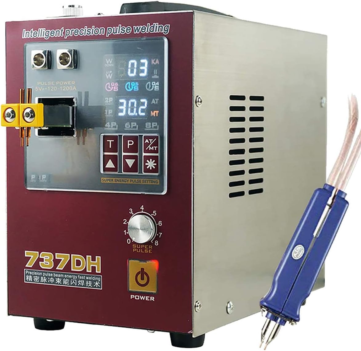
Image: The main unit of the 737DH spot welder with the welding pen attached to the front terminals.
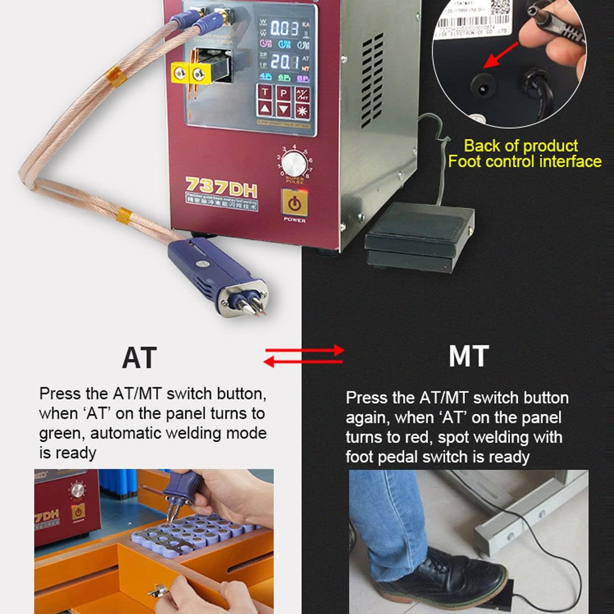
Image: Illustrates the connection point for the foot pedal switch on the rear of the spot welder and the foot pedal itself.
Operating Instructions
Power On/Off
Press the POWER button on the front panel to turn the unit on or off. The display will illuminate when powered on.
Understanding the Display and Controls
The front panel features a digital display and control buttons for adjusting welding parameters.
Image: A detailed view of the spot welder's control panel, showing the digital display, pulse settings, time delay options, and power button.
Welding Modes: AT (Automatic) vs. MT (Manual)
The 737DH offers two welding modes:
- AT Mode (Automatic Welding): Press the AT/MT switch button. When 'AT' on the panel turns green, the automatic welding mode is active. In this mode, the machine detects contact with the workpiece and initiates the weld automatically.
- MT Mode (Manual Spot Welding): Press the AT/MT switch button again. When 'AT' on the panel turns red, the manual spot welding mode is active, requiring the foot pedal switch to initiate a weld.
Image: Demonstrates the difference between AT (automatic) and MT (manual, foot pedal) welding modes, showing the corresponding indicator lights on the display.
Adjusting Pulse Group Settings
The unit allows for adjustment of the pulse group, which affects the welding strength and quality. Options include 4P, 6P, and 8P, allowing for pulse superposition up to 18 pulses.
Use the designated buttons on the control panel to cycle through and select the desired pulse group (e.g., 4P, 6P, 8P). Higher pulse numbers generally result in stronger welds.
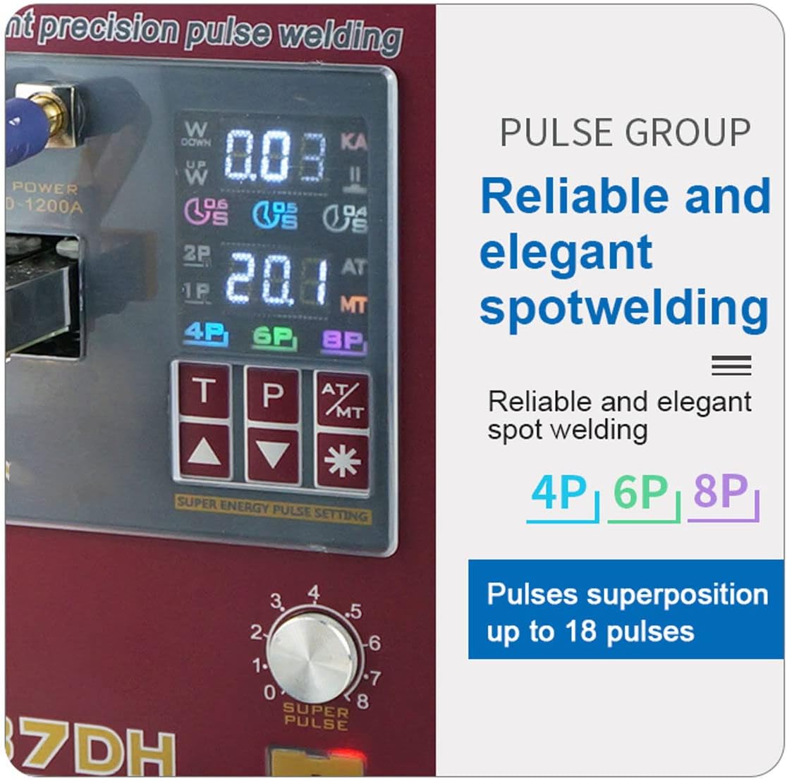
Image: A close-up of the display highlighting the pulse group settings (4P, 6P, 8P) for reliable spot welding.
Adjusting Time Delay Function
The intelligent time delay function allows for precise control over the welding duration. Available settings are 0.4s, 0.5s, and 0.6s, with superposition possible up to 1.5s.
Use the time adjustment buttons (likely labeled 'T' or with up/down arrows) to set the desired delay.

Image: The display showing the time delay options (0.4s, 0.5s, 0.6s) for the "AT" (Time-lapse Spot Welding) mode.
Welding Process
- Prepare Batteries: Ensure batteries are clean and free of debris.
- Prepare Nickel Strips: Cut nickel strips to the appropriate length for your battery pack configuration.
- Position Workpiece: Place the battery and nickel strip securely. For multiple batteries, use the 6-cells battery clamp fixture for stability.
- Select Mode and Settings: Choose either AT or MT mode and adjust pulse group and time delay settings according to the thickness of the nickel strip and desired weld strength. Start with lower settings and increase gradually if needed.
- Perform Weld:
- AT Mode: Gently press the welding pins onto the nickel strip, ensuring good contact with both the strip and the battery terminal. The weld will automatically initiate.
- MT Mode: Gently press the welding pins onto the nickel strip, ensuring good contact. Then, press the foot pedal to initiate the weld.
- Inspect Weld: After each weld, visually inspect the joint for strength and consistency. Adjust settings as necessary.
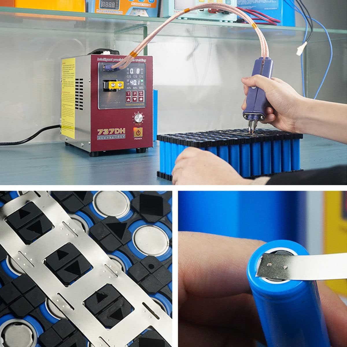
Image: The spot welder being used to attach nickel strips to a series of 18650 batteries, demonstrating the welding process.

Image: A close-up view showing a nickel strip being welded onto the positive terminal of an 18650 battery.

Image: The 737DH spot welder being used with the 6-cells battery clamp fixture to hold batteries during the welding process.
Maintenance
- Cleaning: Regularly clean the welding pins and the main unit with a dry, soft cloth. Ensure no metal dust or debris accumulates on the welding pins or around the electrical contacts.
- Welding Pin Replacement: If welding pins become worn or pitted, replace them with new ones provided or compatible replacements to ensure consistent weld quality.
- Fuse Replacement: If the unit fails to power on or experiences electrical issues, check the fuse. Replace with a fuse of the same rating if necessary.
- Storage: Store the spot welder in a dry, dust-free environment when not in use.
Troubleshooting
- No Power:
- Check if the power cord is securely connected. Verify the power outlet is functional. Check and replace the fuse if blown.
- Poor Weld Quality (Weak or Inconsistent Welds):
- Ensure welding pins are clean and sharp. Adjust pulse group and time delay settings. Increase power settings gradually. Ensure good contact between the welding pins, nickel strip, and battery terminal.
- Overheating:
- Allow the unit to cool down. Ensure adequate ventilation around the machine. Avoid continuous, prolonged welding without breaks.
Warranty and Support
This product comes with a warranty. Please refer to the included "Instruction and Warranty Card" for specific warranty terms, conditions, and contact information for technical support. Keep your purchase receipt as proof of purchase.
Image: The instruction and warranty card, which contains important information regarding product support and warranty coverage.