GOLDEN BLUE DT-9205A
DT-9205A Handheld Digital Multimeter User Manual
Model: DT-9205A | Brand: GOLDEN BLUE
1. Introduction
Thank you for choosing the GOLDEN BLUE DT-9205A Handheld Digital Multimeter. This device is designed for accurate and reliable measurement of various electrical parameters, making it an essential tool for electricians, hobbyists, and professionals. Please read this manual thoroughly before operation to ensure safe and proper use.

Figure 1: Product Introduction and Key Specifications. This image highlights the brand (ANENG, which seems to be a sub-brand or alternative name for GOLDEN BLUE for this product), model (DT-9205A), weight (195g), color (Red), battery type (6F22 9V), included accessories (multimeter/pen/instruction), and dimensions (194.5mm x 90.3mm x 30.3mm).
2. Safety Information
Always observe safety precautions when using any electrical testing equipment. Failure to do so may result in injury or damage to the multimeter or equipment under test.
- Do not exceed the maximum input values for any range.
- Do not use the multimeter if it appears damaged or if the test leads are damaged.
- Exercise extreme caution when working with voltages above 30V AC RMS, 42V peak, or 60V DC. These voltages pose a shock hazard.
- Always disconnect power to the circuit and discharge all high-voltage capacitors before testing resistance, continuity, diodes, or capacitance.
- Ensure the function switch is in the correct position for the desired measurement before connecting the test leads to the circuit.
- Replace the battery when the low battery indicator appears to ensure accurate readings.
- Do not operate the multimeter in explosive gas, vapor, or dust environments.
3. Product Overview
The DT-9205A is a versatile digital multimeter featuring a clear LCD display and a rotary switch for selecting measurement functions. It is designed for ease of use and portability.

Figure 2: Front view of the DT-9205A Digital Multimeter. This image shows the main display, rotary function switch, input jacks (20A, mA, COM, VΩHz), and function buttons (POWER, HOLD).
3.1 Components and Controls
- LCD Display: Shows measurement readings, units, and function indicators.
- Function Rotary Switch: Used to select the desired measurement function (e.g., DCV, ACV, DCA, ACA, Resistance, Capacitance, Frequency, Diode, Triode, Continuity).
- "20A" Input Jack: For current measurements up to 20A.
- "mA" Input Jack: For current measurements up to 200mA.
- "COM" (Common) Input Jack: The negative (-) input for all measurements.
- "VΩHz" Input Jack: The positive (+) input for voltage, resistance, frequency, capacitance, diode, and continuity measurements.
- POWER Button: Turns the multimeter on/off.
- HOLD Button: Freezes the current reading on the display.
4. Setup
4.1 Battery Installation
The DT-9205A requires one 6F22 9V battery (not included). To install the battery:
- Locate the battery compartment cover on the back of the multimeter.
- Use a screwdriver to remove the screw securing the cover.
- Gently remove the cover.
- Connect the 9V battery to the battery clip, observing correct polarity.
- Place the battery into the compartment and replace the cover, securing it with the screw.

Figure 3: Multimeter with included accessories. This image shows the DT-9205A multimeter, a pair of red and black test leads, and the operator's instruction manual.
4.2 Connecting Test Leads
Always connect the black test lead to the "COM" (Common) input jack. Connect the red test lead to the appropriate input jack based on the measurement you intend to perform:
- For Voltage, Resistance, Capacitance, Frequency, Diode, and Continuity measurements: Connect the red lead to the "VΩHz" jack.
- For Current measurements (up to 200mA): Connect the red lead to the "mA" jack.
- For High Current measurements (up to 20A): Connect the red lead to the "20A" jack.
5. Operating Instructions
Before taking any measurement, ensure the test leads are correctly connected and the function switch is set to the desired range.
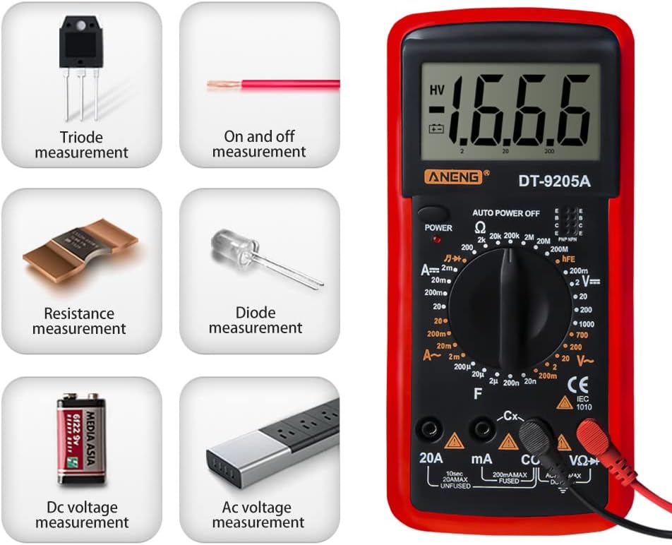
Figure 4: Overview of measurement capabilities. This image illustrates the various types of measurements the DT-9205A can perform, including Triode, On and Off (Continuity), Resistance, Diode, DC Voltage, and AC Voltage measurements.
5.1 DC Voltage Measurement
To measure DC voltage:
- Connect the black test lead to the "COM" jack and the red test lead to the "VΩHz" jack.
- Set the rotary switch to the desired DCV range (e.g., 200mV, 2V, 20V, 200V, 1000V). If the voltage is unknown, start with the highest range and work downwards.
- Connect the test leads across the component or circuit to be measured, observing polarity.
- Read the voltage value on the LCD display.
5.2 AC Voltage Measurement
To measure AC voltage:
- Connect the black test lead to the "COM" jack and the red test lead to the "VΩHz" jack.
- Set the rotary switch to the desired ACV range (e.g., 20V, 200V, 750V). Start with the highest range if the voltage is unknown.
- Connect the test leads across the AC voltage source.
- Read the voltage value on the LCD display.

Figure 5: AC Voltage Measurement. This image demonstrates the DT-9205A multimeter measuring AC voltage from a standard wall outlet, showing a reading of 227V.
5.3 DC Current Measurement
To measure DC current:
- IMPORTANT: Turn off power to the circuit before connecting the multimeter.
- Connect the black test lead to the "COM" jack. Connect the red test lead to the "mA" jack for currents up to 200mA, or to the "20A" jack for currents up to 20A.
- Set the rotary switch to the desired DCA range (e.g., 20mA, 200mA, 20A).
- Open the circuit where you want to measure current and connect the multimeter in series with the load.
- Apply power to the circuit and read the current value on the LCD display.
5.4 AC Current Measurement
To measure AC current:
- IMPORTANT: Turn off power to the circuit before connecting the multimeter.
- Connect the black test lead to the "COM" jack. Connect the red test lead to the "mA" jack for currents up to 200mA, or to the "20A" jack for currents up to 20A.
- Set the rotary switch to the desired ACA range (e.g., 200mA, 20A).
- Open the circuit where you want to measure current and connect the multimeter in series with the load.
- Apply power to the circuit and read the current value on the LCD display.
5.5 Resistance Measurement
To measure resistance:
- IMPORTANT: Ensure the circuit is de-energized and all capacitors are discharged before measuring resistance.
- Connect the black test lead to the "COM" jack and the red test lead to the "VΩHz" jack.
- Set the rotary switch to the desired Ohm (Ω) range (e.g., 200Ω, 2kΩ, 20kΩ, 200kΩ, 2MΩ, 20MΩ).
- Connect the test leads across the resistor or component.
- Read the resistance value on the LCD display.
5.6 Capacitance Measurement
To measure capacitance:
- IMPORTANT: Ensure the capacitor is fully discharged before measurement.
- Connect the black test lead to the "COM" jack and the red test lead to the "VΩHz" jack.
- Set the rotary switch to the desired Capacitance (F) range (e.g., 2nF, 20nF, 200nF, 2µF, 20µF).
- Connect the test leads across the capacitor terminals.
- Read the capacitance value on the LCD display.
5.7 Frequency Measurement
To measure frequency:
- Connect the black test lead to the "COM" jack and the red test lead to the "VΩHz" jack.
- Set the rotary switch to the Frequency (Hz) range.
- Connect the test leads across the signal source.
- Read the frequency value on the LCD display.
5.8 Diode Test
To perform a diode test:
- IMPORTANT: Ensure the diode is disconnected from the circuit and de-energized.
- Connect the black test lead to the "COM" jack and the red test lead to the "VΩHz" jack.
- Set the rotary switch to the Diode (►|) position.
- Connect the red lead to the anode and the black lead to the cathode of the diode. The display will show the forward voltage drop.
- Reverse the leads. The display should show "OL" (Open Loop) for a good diode.

Figure 6: Diode Measurement. This image illustrates how to perform a diode measurement by inserting the test leads into the corresponding input jacks and connecting them to the diode.
5.9 Triode (hFE) Test
To test a triode (transistor) hFE:
- Set the rotary switch to the hFE position.
- Identify if the transistor is NPN or PNP.
- Insert the transistor's emitter, base, and collector leads into the corresponding holes in the hFE socket on the multimeter.
- Read the hFE value on the LCD display.
5.10 Continuity Test
To perform a continuity test:
- IMPORTANT: Ensure the circuit is de-energized.
- Connect the black test lead to the "COM" jack and the red test lead to the "VΩHz" jack.
- Set the rotary switch to the Continuity (♫) position.
- Connect the test leads across the circuit or component.
- If there is continuity (low resistance), the multimeter will emit an audible beep and display a low resistance value. If open, it will display "OL".
5.11 Data Hold Function
Press the "HOLD" button to freeze the current reading on the display. Press it again to release the hold and resume live measurements.
6. Maintenance
6.1 Cleaning
Wipe the case with a damp cloth and mild detergent. Do not use abrasives or solvents. Keep the input terminals clean to prevent inaccurate readings.
6.2 Battery Replacement
When the low battery indicator appears on the display, replace the 9V battery as described in the "Battery Installation" section (4.1). A low battery can lead to inaccurate readings.
6.3 Fuse Replacement
If the current measurement function does not work, the fuse may be blown. Refer to the specifications for fuse type and rating. To replace the fuse, open the back cover (similar to battery replacement) and carefully replace the fuse with one of the same type and rating.
6.4 Storage
If the multimeter is not to be used for a long period, remove the battery to prevent leakage and damage to the device. Store the multimeter in a cool, dry place away from direct sunlight and extreme temperatures.
7. Troubleshooting
| Problem | Possible Cause | Solution |
|---|---|---|
| No display or dim display | Low or dead battery; Power button not pressed. | Replace battery; Press POWER button. |
| "OL" (Overload) displayed | Input value exceeds selected range; Open circuit (for continuity/resistance). | Select a higher range; Check circuit connection. |
| Inaccurate readings | Low battery; Dirty test leads/jacks; Incorrect range selected. | Replace battery; Clean leads/jacks; Select appropriate range. |
| Current measurement not working | Blown fuse; Incorrect input jack used. | Check and replace fuse; Ensure red lead is in "mA" or "20A" jack. |
8. Specifications

Figure 7: Product Dimensions. This image provides the physical dimensions of the DT-9205A multimeter: 194.5mm (7.65in) length, 90.3mm (3.55in) width, and 30.3mm (1.19in) thickness.
| Parameter | Range / Value | Accuracy |
|---|---|---|
| DC Voltage | 200mV - 1000V | (0.5%+1dgt) |
| AC Voltage | 20V - 750V | (0.8%+3dgt) |
| DC Current | 20mA - 20A | (0.8%+1dgt) |
| AC Current | 200mA - 20A | (1.8%+3dgt) |
| Resistance | 200Ω - 200MΩ | (0.8%+1dgt) |
| Capacitance | 2nF - 20µF | (2.5%+3dgt) |
| Frequency | 2KHz - 20KHz | (1.5%+5dgt) |
| Diode Test | Yes | |
| Triode Test | Yes | |
| Continuity Test | Yes | |
| Sleep Mode | Yes | |
| Data Hold | Yes | |
| Maximum Display | 1999 | |
| Power Supply | 6F22 9V battery | |
| Color | Red | |
| Dimensions (L x W x T) | 194.5mm x 90.3mm x 30.3mm | |
| Weight | 195g (approx.) |
9. Warranty and Support
For warranty information and technical support, please refer to the documentation included with your purchase or contact GOLDEN BLUE customer service. Keep your purchase receipt as proof of purchase.
For further assistance, please visit the GOLDEN BLUE Store on Amazon.