Lelukee Lelukee22020406
Lelukee Water Flow Totalizer and Flow Rate Meter User Manual
Model: Lelukee22020406
1. Product Overview
The Lelukee Water Flow Totalizer and Flow Rate Meter is a digital LCD display unit designed for accurate measurement of liquid water flow. It includes a G1/2" Hall Effect flowmeter sensor and a control unit, capable of displaying flow rate, total water consumption, and temperature.

Image 1.1: The Lelukee Water Flow Totalizer and Flow Rate Meter, showing the digital display unit and the G1/2" Hall Effect flowmeter sensor.
2. Package Contents
- 1 x LCD flow display controller
- 1 x G1/2 inch flowmeter sensor
3. Setup and Installation
Follow these steps for proper installation of your water flow totalizer and meter:
- Sensor Placement: Install the G1/2" Hall Effect flowmeter sensor in the water line. Ensure the flow direction matches the arrow indicated on the sensor body. Use appropriate fittings and apply Teflon tape to threads to prevent leaks.
- Temperature Probe: Connect the temperature detection wire head to the designated port on the display controller.
- Power Supply: The system is powered by AAA batteries (not included). Ensure batteries are inserted with correct polarity. The operating voltage range for the display controller is DC24V±8/1A.
- Solenoid Valve (Optional): If using a solenoid valve, connect it to the display controller. The solenoid valve working voltage is DC12V / 0.3A-0.5A (normally closed).

Image 3.1: Connection points on the flow meter and sensor, highlighting the G1/2" thread and the temperature probe connection.
4. Operating Instructions
The digital LCD display provides real-time information and allows for various settings adjustments.
4.1 Display Functions
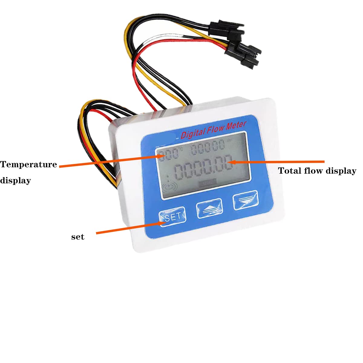
Image 4.1: Close-up of the digital display, indicating the temperature display, total flow display, and the 'SET' button.
- Temperature Display: The top left of the display shows the temperature, ranging from -99° to 999°. The unit can be Celsius (C) or Fahrenheit (F).
- Total Flow Display: The main part of the display shows the total water consumption. The unit can be Liters (L) or Gallons (GAL).
- Flow Rate Display: The current flow rate is also displayed.
4.2 Unit Switching
- Temperature Unit (C/F): Short press the "+" key to switch between Celsius and Fahrenheit.
- Total Water Consumption Unit (L/GAL): The unit for total water consumption can be toggled between Liters (L) and Gallons (GAL). Refer to the device's specific button for this function, often indicated by a unit symbol.
4.3 K-Value Setting
The K-value setting character (K SETTING) will be displayed when entering the K-value setting interface. This value is crucial for calibration and accurate flow measurement. Consult specific calibration instructions if available or refer to the product's technical documentation for details on adjusting the K-value.
5. Maintenance
To ensure optimal performance and longevity of your device:
- Keep the display unit clean and dry.
- Ensure the water pressure does not exceed 1.75Mpa to prevent damage to the sensor.
- The long-term operating temperature for water should not exceed 60°C.
- When not in use and no water is flowing, the system will enter a sleep mode to conserve battery power.
6. Troubleshooting
6.1 Total Water Consumption Reset
There are two methods to reset the total water consumption:
- Hardware Reset: Locate the "RESET" symbol on the back of the circuit board. There are two contacts next to it. Shorting these two contacts after the system is powered on will clear the total water consumption.
- Software Reset: Press and hold the "SET" button. After the displayed number flashes, use the "+" and "-" buttons to modify the value to 0.
6.2 Inconsistent Unit Display
If the unit automatically reverts after switching (e.g., from Liters to Gallons), ensure that the unit setting is properly saved or confirmed according to the operating instructions. If the issue persists, try a total water consumption reset.
6.3 Leaks at Connections
Ensure that G1/2" fittings are used correctly and that sufficient Teflon tape is applied to all threaded connections during installation to prevent leaks.
7. Specifications
| Feature | Specification |
|---|---|
| Operating Voltage Range | DC24V±8/1A |
| Flow Range | 1-30 L/min (Sensor: 1-25 L/min) |
| Water Pressure | ≤1.75 Mpa |
| LCD Size | 3 inch, built-in backlight |
| Case Size (Display) | 100 x 75 x 35 mm (39.3 x 29.5 x 13.7 inch) |
| Solenoid Valve Working Voltage | DC12V / 0.3A-0.5A (normally closed) |
| Temperature Display Range | -99° to 999° |
| Applicable Liquid Temperature | Not more than 60°C (for long-term use) |
| Voltage and Current | DC4.5 ~ 24V, current ≤ 10mA |
| Insulation Resistance | > 100 MΩ |
| Output Pulse High Level | ≥ DC 4.5V (input voltage DC 5V) |
| Item Model Number | Lelukee22020406 |
| Package Dimensions | 6.42 x 5.43 x 2.17 inches; 8.11 ounces |

Image 7.1: Detailed specifications for the water flow sensor, including object/temperature, flow range, water pressure, voltage, insulation resistance, and output pulse level.

Image 7.2: Technical drawing showing the dimensions of the digital flow meter display unit.

Image 7.3: Technical drawing illustrating the dimensions of the G1/2 inch water flow sensor.
8. Warranty and Support
For warranty information or technical support, please refer to the product packaging or contact Lelukee customer service through their official channels. Keep your purchase receipt for warranty claims.
Ask a question about this manual
Ask about setup, troubleshooting, compatibility, parts, safety, or missing instructions. Manuals+ will review the question and use this page’s manual context to help answer it.