
Mollom G75-220V
MOLLOM VFD 220V 5.5KW 7.5HP Variable Frequency Drive User Manual
Model: G75-220V
1. Introduction
This manual provides essential information for the safe and efficient operation of your MOLLOM 220V 5.5KW 7.5HP Variable Frequency Drive (VFD). Please read this manual thoroughly before installation, operation, or maintenance to ensure proper usage and prevent potential hazards.
The MOLLOM VFD is designed to control the speed of three-phase AC motors, offering precise control for various applications such as CNC routers, milling machines, and pumps. It supports both single-phase and three-phase 220V input.
2. Safety Precautions
Always observe the following safety precautions to prevent personal injury or damage to the equipment.
- Electrical Hazard: Ensure power is disconnected before wiring or performing maintenance. Only qualified personnel should perform electrical work.
- Grounding: The VFD must be properly grounded to prevent electric shock.
- Motor Connection: The frequency converter must be directly connected to the motor. Control motor start/stop exclusively through the VFD to avoid damage.
- Environment: Avoid operating the VFD in humid environments, or where water mist, water droplets, or metal objects may fall into the unit, as this can cause short circuits.
- External Resistor: If your motor operates under heavy load, consider using an external braking resistor.
3. Specifications
| Feature | Specification |
|---|---|
| Power | 5.5KW (7.5HP) |
| Input Voltage | AC 220V (±15%) |
| Output Voltage | AC 220V |
| Maximum Output Current | 25A |
| Input Frequency | 50/60 Hz |
| Output Frequency | 0-3000 Hz |
| Input Phase | Single or Three Phase |
| Output Phase | Three-phase |
| Dimensions (L x W x H) | 5.9 x 7.3 x 10.2 inches (150 x 185 x 260 mm) |
| Model Number | G75-220V |
| Display Type | Digital |
| Material | Acrylonitrile Butadiene Styrene (ABS) |
4. Product Components and Dimensions
The MOLLOM VFD unit includes the main inverter and a detachable control panel. Below are images illustrating the unit's appearance and dimensions.

Figure 4.1: Front view of the MOLLOM VFD 5.5KW 7.5HP unit. This image shows the main body of the Variable Frequency Drive with its control panel integrated, displaying the brand logo and warning symbols.

Figure 4.2: Dimensions of the MOLLOM VFD. This image provides a side view of the VFD unit with measurements indicating its length (10.2 inches), width (7.3 inches), and depth (5.9 inches).

Figure 4.3: Detailed view of the VFD control panel. This image highlights the various buttons and indicators on the control panel, including the State LED, Unit LED, Code Display, UP/DOWN buttons, Potentiometer, PRG (Programming/Return), ENTER, SHIFT-Right, RUN, MF.K (Function/Jog), and STOP/RST (Stop/Reset) buttons.

Figure 4.4: MOLLOM VFD with its detachable control panel. This image shows the main VFD unit alongside its separated control panel, illustrating the remote control capability.
5. Setup and Wiring
Proper wiring is crucial for the safe and correct operation of the VFD. Refer to the wiring diagram below and follow these instructions carefully.

Figure 5.1: Wiring diagram for connecting the VFD to a motor. This diagram illustrates the connections for single or three-phase 220V input (R, S, T terminals), grounding (PE terminal), three-phase 220V output to the motor (U, V, W terminals), and optional braking resistor connections (P+, BR terminals).
5.1 Input Power Connection
- Connect the AC 220V input power to the terminals labeled R, S, and T.
- For single-phase 220V input, connect the live wire to R and the neutral wire to T (or L and N if labeled differently).
- For three-phase 220V input, connect each phase to R, S, and T respectively.
- Ensure proper circuit breakers are installed upstream for protection.
5.2 Motor Connection
- Connect the three-phase motor wires to the VFD output terminals labeled U, V, and W.
- Refer to your motor's wiring diagram to ensure it is configured for 220V operation (typically Delta connection for 220V).
- If the motor rotates in the wrong direction, you can swap any two of the U, V, W output wires, or adjust the rotation direction in the VFD's parameters.
- Important: The motor must be directly connected to the VFD. Do not place any switches or contactors between the VFD and the motor.
5.3 Grounding
- Connect the ground wire from your power supply and the motor frame to the VFD's PE (Protective Earth) terminal.
- Ensure a solid, low-impedance ground connection.
5.4 Braking Resistor (Optional)
- For applications requiring rapid deceleration or operating with high inertia loads, an external braking resistor can be connected to terminals P+ and BR.
- Consult the VFD specifications and your application requirements to select an appropriate braking resistor.
6. Operation
This section covers basic operation and parameter settings for the MOLLOM VFD.
6.1 Control Panel Functions
- PRG (Programming/Return): Enters/exits parameter setting mode, or returns to the previous menu.
- ENTER: Confirms parameter changes or enters sub-menus.
- UP/DOWN Arrows: Navigate through parameters or adjust values.
- SHIFT-Right: Shifts the cursor during parameter value entry.
- RUN: Starts the motor.
- STOP/RST: Stops the motor or resets fault conditions.
- MF.K (Function/Jog): Activates special functions or jog mode.
- Potentiometer: Adjusts the output frequency (speed) in manual mode.
6.2 Basic Parameter Setting
The VFD comes with default settings. You may need to adjust certain parameters for your specific motor and application. Common parameters include:
- P0.03: Control mode selection (e.g., V/F control, vector control).
- P0.04: Maximum output frequency (e.g., 60Hz for standard motors).
- P0.10: Accelerating time.
- P0.11: Decelerating time.
- F0.02: Factory reset.
For detailed parameter descriptions and advanced settings, refer to the comprehensive user manual PDF available for download or contact technical support.

Figure 6.1: Example of VFD parameter settings for spindle control. This image displays a table of various parameters (e.g., P0.03, P0.04, P0.10, F0.02) with their setting ranges and instructions, useful for configuring the VFD for specific applications like CNC spindle motors.
6.3 Starting and Stopping the Motor
- Start: Press the RUN button on the control panel.
- Stop: Press the STOP/RST button on the control panel.
- Adjust motor speed using the potentiometer or programmed external controls.
7. Maintenance
Regular maintenance ensures the longevity and reliable operation of your VFD.
- Cleaning: Keep the VFD clean and free from dust and debris. Use a soft, dry cloth for cleaning. Do not use liquid cleaners.
- Ventilation: Ensure adequate airflow around the VFD. Regularly check that cooling fans and vents are not obstructed.
- Connections: Periodically check all electrical connections for tightness. Loose connections can cause overheating or intermittent operation.
- Environmental Check: Verify that the operating environment remains within specified temperature and humidity ranges.
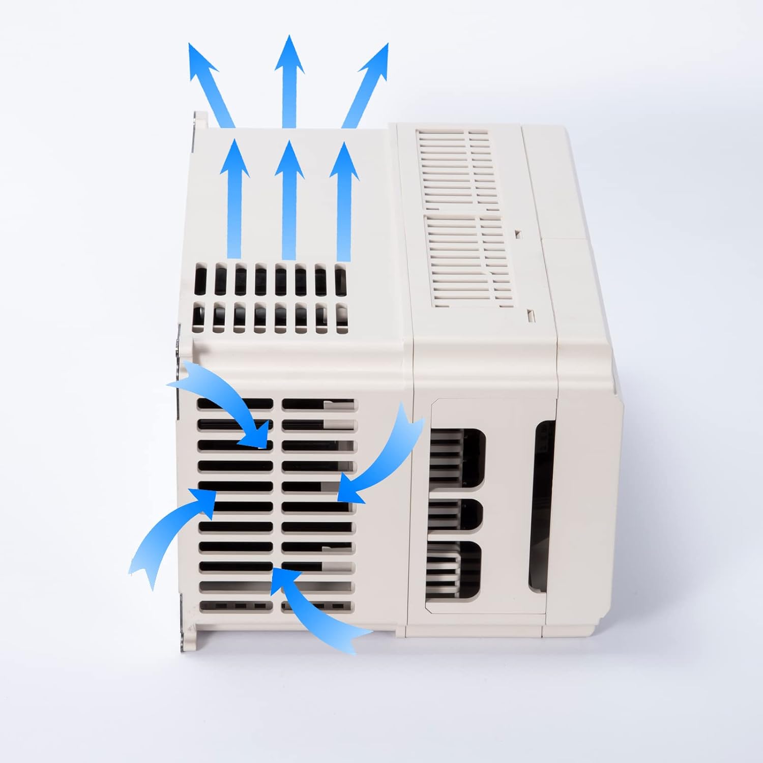
Figure 7.1: Illustration of the VFD's cooling airflow. This image shows blue arrows indicating the path of air entering through the side vents and exiting through the top, demonstrating the cooling mechanism of the unit.
8. Troubleshooting
This section provides guidance for common issues. For complex problems, contact technical support.
| Problem | Possible Cause | Solution |
|---|---|---|
| VFD does not power on | No input power; Blown fuse/breaker; Incorrect wiring | Check power supply; Inspect fuses/breakers; Verify input wiring (R, S, T). |
| Motor does not start | Incorrect parameters; Emergency stop active; Motor wiring error | Check motor parameters (e.g., frequency, voltage); Ensure no emergency stop is engaged; Verify motor connections (U, V, W). |
| Motor runs in wrong direction | Motor phase sequence incorrect | Swap any two of the U, V, W output wires, or change direction parameter in VFD settings. |
| Overcurrent/Overload fault | Motor overload; Short circuit; Acceleration time too short | Reduce motor load; Check motor and wiring for shorts; Increase acceleration time parameter. |
| Overvoltage fault | Deceleration time too short; High inertia load without braking resistor | Increase deceleration time; Install or check braking resistor. |
9. Technical Support and Warranty
For further assistance with parameter settings, troubleshooting, or any other technical inquiries, please contact MOLLOM customer support.
When contacting support, please provide your VFD model number (G75-220V) and a detailed description of your issue, including any error codes displayed on the VFD.
A comprehensive user manual in PDF format is also available for download: MOLLOM VFD User Manual (PDF).
Warranty Information: Please refer to the warranty card included with your product or contact MOLLOM customer service for details regarding warranty coverage and terms.

Figure 9.1: Illustration representing technical support. This image shows a stylized figure interacting with a parameter setting screen, symbolizing the availability of assistance for VFD configuration.
Ask a question about this manual
Ask about setup, troubleshooting, compatibility, parts, safety, or missing instructions. Manuals+ will review the question and use this page’s manual context to help answer it.