1. Introduction
This manual provides essential information for the safe and effective use of Generic CNMG120404 HA H01 carbide inserts. These inserts are designed for external turning applications, specifically optimized for cutting aluminum and copper. They feature a CVD coating and a hardness rating of 95, ensuring high strength, performance, and wear resistance for a long service life in appropriate machining conditions.
Always verify the item's specifications, including angle, coating, hardness, and intended usage, before installation and operation.
2. Setup and Installation
Proper installation is crucial for optimal performance and safety. Follow these steps:
- Safety First: Ensure the lathe machine is powered off and secured to prevent accidental startup during installation.
- Tool Holder Selection: Select a compatible tool holder designed for CNMG-style inserts. Ensure the tool holder is clean and free from debris.
- Insert Placement: Carefully place the CNMG120404 HA H01 insert into the designated pocket of the tool holder. Ensure it sits flush and correctly oriented.
- Securing the Insert: Use the appropriate screw or clamping mechanism to secure the insert. Tighten the screw firmly but avoid overtightening, which can damage the insert or tool holder.
- Verification: Visually inspect the installed insert to confirm it is stable, properly seated, and free from any wobble.
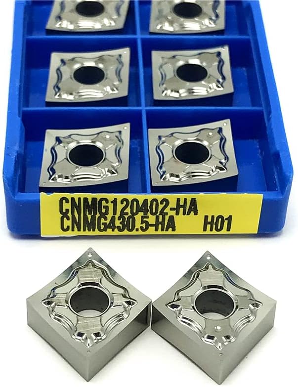
Image 1: CNMG120404 HA H01 Carbide Inserts in packaging and individually. The image displays a blue plastic case holding several square-shaped carbide turning inserts. Below the case, two identical inserts are shown, emphasizing their precise geometry, polished surfaces, and the central hole for mounting. A yellow label on the case provides model information.
3. Operating Instructions
Adhere to these guidelines for safe and efficient operation:
- Personal Protective Equipment (PPE): Always wear appropriate PPE, including safety glasses, gloves, and hearing protection, during machining operations.
- Workpiece Security: Ensure the workpiece is securely clamped in the lathe chuck or fixture to prevent movement during cutting.
- Cutting Parameters: Set appropriate cutting parameters (spindle speed, feed rate, and depth of cut) based on the workpiece material (e.g., aluminum, copper), desired surface finish, and machine capabilities. Consult machining handbooks or material data sheets for recommended starting parameters.
- Initiate Cutting: Begin cutting gradually, observing chip formation. Ideal chips should be consistent and manageable.
- Monitoring: Continuously monitor the cutting process for signs of excessive vibration, unusual noise, or poor chip evacuation, which may indicate incorrect parameters or a worn insert.
- Insert Replacement: Replace inserts promptly when signs of wear (e.g., chipping, excessive flank wear, poor surface finish) are observed. Continuing to use a worn insert can lead to poor part quality, increased tool pressure, and potential tool failure.
4. Maintenance
Proper maintenance extends the life of your inserts and ensures consistent performance:
- Cleaning: After each use, clean the inserts and tool holder to remove chips, coolant residue, and other debris. Use a brush or compressed air.
- Storage: Store unused or spare inserts in their original protective packaging in a dry, clean environment to prevent damage from moisture, dust, or accidental impact.
- Inspection: Before each use, visually inspect inserts for any signs of damage, chipping, or excessive wear. Do not use damaged inserts.
5. Troubleshooting
Refer to the following table for common issues and their potential solutions:
| Issue | Possible Cause | Solution |
|---|---|---|
| Poor Surface Finish | Worn or chipped insert, incorrect cutting parameters (speed, feed), excessive vibration, insufficient coolant. | Replace insert, adjust cutting speed and feed rate, check tool holding rigidity, ensure adequate coolant flow. |
| Excessive Tool Wear | Cutting parameters too aggressive, abrasive workpiece material, lack of coolant, incorrect insert grade. | Optimize cutting parameters, ensure proper coolant application, consider a different insert grade if material is highly abrasive. |
| Chip Breaking Issues | Incorrect feed rate, chip breaker geometry unsuitable for material, insufficient depth of cut. | Adjust feed rate, ensure the correct chip breaker geometry is selected for the specific material and application, increase depth of cut if possible. |
| Vibration/Chatter | Unstable setup, worn machine components, incorrect cutting parameters, long tool overhang. | Check tool holder and workpiece clamping rigidity, reduce tool overhang, adjust cutting parameters (speed, feed, depth of cut). |
6. Specifications
- Model: CNMG120404 HA H01
- Angle: CNMG120404 HA H01 (referring to the specific geometry and grade)
- Coating: CVD
- Hardness: 95
- Usage: External Turning Tool
- Material: Carbide
- Package Quantity: 10 Pieces
- ASIN: B09Z8LLGDG
- Date First Available: May 3, 2022
7. Warranty Information
No specific warranty information is provided with this product. Please refer to the retailer's return policy for details regarding returns or exchanges.
8. Customer Support
For further assistance or inquiries, please contact the seller or retailer from whom the product was purchased. No direct manufacturer support contact information is available in this manual.


