1. Introduction
This manual provides essential information for setting up, operating, and maintaining your Fasizi ESP32 WiFi Kit 32 V3 Development Board. This board is designed for Internet of Things (IoT) applications, featuring an ESP32-S3FN8 dual-core processor, integrated Wi-Fi and Bluetooth, and a 0.96-inch OLED display. It is compatible with various development environments, including Arduino.
2. Product Overview
2.1 Key Features
- Microprocessor: ESP32-S3FN8 (32-bit LX7 dual-core processor, five-stage pipeline rack structure, main frequency up to 240 MHz).
- Connectivity: Integrated 2.4 GHz Wi-Fi (802.11 b/g/n, up to 150 Mbps) and Bluetooth LE (Bluetooth 5, Bluetooth mesh).
- Display: Integrated 0.96-inch 128x64 dot matrix OLED display for debugging and information.
- USB Interface: Type-C USB with full voltage regulator, ESD protection, short-circuit protection, and RF shielding.
- Power Management: Integrated SH1.25-2 battery interface and lithium battery management system.
- Hardware Resources: 7*ADC1+2*ADC2; 7* Touch; 3*UART; 2*I2C; 2*SPI, etc.
- Memory: 384 KB ROM; 512 KB SRAM; 16 KB RTC SRAM; 8 MB SiP Flash.
2.2 Board Components
The Fasizi ESP32 WiFi Kit 32 V3 board integrates several key components for versatile development.
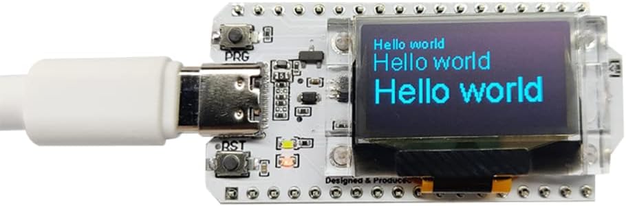
Figure 1: Fasizi ESP32 WiFi Kit 32 V3 Development Board with its 0.96-inch OLED display active, showing "Hello world" text. The board is connected via a USB-C cable.

Figure 2: Top-down view of the Fasizi ESP32 WiFi Kit 32 V3 Development Board, highlighting the ESP32-S3FN8 chip, Wi-Fi antenna, and various components.
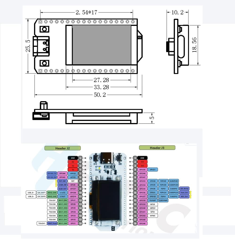
Figure 3: Detailed diagram showing the physical dimensions and pinout configuration of the Fasizi ESP32 WiFi Kit 32 V3 Development Board. This includes GPIO assignments for various functions.
3. Setup Guide
3.1 Initial Connection
- Connect the Fasizi ESP32 WiFi Kit 32 V3 board to your computer using a USB-C cable. The board will draw power from the USB connection.
- Ensure your operating system recognizes the board. If not, you may need to install the CP2102 USB to UART Bridge VCP Drivers. These drivers are typically available from Silicon Labs' official website.
3.2 Development Environment Setup
The ESP32 WiFi Kit 32 V3 is compatible with popular development environments such as Arduino IDE and PlatformIO.
3.2.1 Arduino IDE Setup
- Download and install the latest version of the Arduino IDE from the official Arduino website.
- Open the Arduino IDE. Go to File > Preferences.
- In the "Additional Boards Manager URLs" field, add the ESP32 board manager URL. (Search online for the latest ESP32 board manager URL for Arduino IDE).
- Go to Tools > Board > Boards Manager.... Search for "ESP32" and install the "ESP32 by Espressif Systems" package.
- After installation, select your board from Tools > Board > ESP32 Arduino > ESP32 Dev Module (or a similar option that matches your board's specifications, often "ESP32 WROOM Module" or "ESP32-S3 Dev Module").
- Select the correct COM port under Tools > Port.
- Install the necessary libraries for the OLED display (e.g., Adafruit SSD1306 and Adafruit GFX Library) via Sketch > Include Library > Manage Libraries....
3.2.2 PlatformIO Setup
- Install VS Code.
- Install the PlatformIO IDE extension in VS Code.
- Create a new PlatformIO project and select the appropriate ESP32-S3 board (e.g., "ESP32-S3-DevKitC-1" or similar, depending on the exact chip variant and available board definitions).
- PlatformIO will automatically handle toolchain and library installations.
4. Operating Instructions
4.1 Basic Program Upload
- After setting up your development environment, open an example sketch (e.g., File > Examples > 01.Basics > Blink in Arduino IDE).
- Modify the sketch to include OLED display initialization and text output if desired. For example, to display "Hello World" on the OLED:
#include <Wire.h> #include <Adafruit_GFX.h> #include <Adafruit_SSD1306.h> #define OLED_RESET -1 // Reset pin # (or -1 if sharing Arduino reset pin) Adafruit_SSD1306 display(128, 64, &Wire, OLED_RESET); void setup() { Serial.begin(115200); if(!display.begin(SSD1306_SWITCHCAPVCC, 0x3C)) { // Address 0x3C for 128x64 Serial.println(F("SSD1306 allocation failed")); for(;;); // Don't proceed, loop forever } display.display(); delay(2000); // Pause for 2 seconds display.clearDisplay(); display.setTextSize(1); display.setTextColor(SSD1306_WHITE); display.setCursor(0,0); display.println("Hello, world!"); display.display(); } void loop() { // Your main code here } - Click the "Upload" button in your IDE. The board will automatically enter bootloader mode. If upload fails, press and hold the "BOOT" button (often labeled "PRG") while pressing and releasing the "RESET" button, then release "BOOT".
- Monitor the serial output (Tools > Serial Monitor) for debugging information.
4.2 Wi-Fi and Bluetooth Usage
The ESP32-S3FN8 chip provides robust Wi-Fi and Bluetooth capabilities.
- Wi-Fi: Use the standard ESP32 Wi-Fi libraries in Arduino IDE or PlatformIO to connect to networks, host access points, or implement Wi-Fi-based communication protocols.
- Bluetooth: Utilize the ESP32 Bluetooth libraries for Bluetooth Low Energy (BLE) applications, including advertising, scanning, and GATT client/server roles.
4.3 Powering the Board
The board can be powered via the USB-C port or through the integrated SH1.25-2 battery interface.
- USB-C: Provides 5V power directly from your computer or a USB power adapter.
- Battery: Connect a compatible 3.7V LiPo battery to the SH1.25-2 connector. The board includes a battery management system for charging and protection.
5. Maintenance
- Cleaning: Keep the board clean and free from dust and debris. Use a soft, dry brush or compressed air for cleaning. Avoid using liquids.
- Storage: Store the board in an anti-static bag when not in use to prevent electrostatic discharge damage.
- Firmware Updates: Regularly check for updates to the ESP32 core and libraries in your development environment to ensure you have the latest features and bug fixes.
- Physical Handling: Handle the board by its edges to avoid touching sensitive components, especially when powered.
6. Troubleshooting
- Board Not Recognized by Computer:
- Ensure the USB-C cable is fully inserted and functional.
- Install the CP2102 drivers if not already installed.
- Try a different USB port or computer.
- Program Upload Fails:
- Verify that the correct board and COM port are selected in your IDE.
- Ensure no other application is using the serial port.
- Manually put the board into bootloader mode: press and hold the "PRG" (BOOT) button, then press and release the "RST" button, then release "PRG".
- Check for syntax errors in your code.
- OLED Display Not Working:
- Ensure the OLED library (e.g., Adafruit SSD1306) is correctly installed and initialized in your code.
- Verify the I2C address (commonly 0x3C or 0x3D) in your code matches the display.
- Check for proper power supply to the board.
- Wi-Fi Connection Issues:
- Double-check Wi-Fi credentials (SSID and password).
- Ensure the Wi-Fi network is within range and operating on 2.4 GHz.
- Verify that the Wi-Fi antenna on the PCB is not obstructed or damaged.
- Board Becomes Unresponsive:
- Press the "RST" button to reset the board.
- Disconnect and reconnect the USB power.
- Re-upload a known working simple sketch (e.g., Blink) to rule out software issues.
7. Specifications
| Feature | Specification |
|---|---|
| Main Chip | ESP32-S3FN8 (32-bit LX7 dual-core processor) |
| Serial Chip | CP2102 |
| Wi-Fi | 802.11 b/g/n, up to 150 Mbps |
| Bluetooth | Bluetooth LE (Bluetooth 5, Bluetooth Mesh) |
| OLED Display | 0.96-inch, 128x64 dot matrix |
| ROM | 384 KB |
| SRAM | 512 KB |
| RTC SRAM | 16 KB |
| SiP Flash | 8 MB |
| USB Port | Type-C |
| Operating Temperature | -20°C to 70°C |
| Dimensions (L x W x H) | 50.2 x 25.5 x 10.2 mm |
| Weight | 60 grams |
| Hardware Platform | Arduino |
| Operating System Compatibility | Linux (and typically Windows, macOS) |
8. Warranty and Support
8.1 Warranty Information
Specific warranty details for the Fasizi ESP32 WiFi Kit 32 V3 Development Board may vary depending on the retailer and region of purchase. Please refer to your purchase documentation or contact the seller for precise warranty terms. Generally, electronic components are covered against manufacturing defects for a limited period.
8.2 Technical Support
For technical assistance, programming guides, or community support, please refer to the extensive online resources available for ESP32 development boards. These include:
- Official Espressif Systems documentation and forums.
- Arduino ESP32 community forums.
- PlatformIO documentation and community.
- Numerous online tutorials and project guides for ESP32 and OLED displays.
If you encounter issues that cannot be resolved through these resources, contact your point of purchase for further assistance.