1. Introduction
Thank you for choosing the Fasizi FR120N MOS Module. This module is a MOSFET-based control unit designed for switching high-power loads using low-power control signals. It features decoupled isolation to minimize interference between the control signal and the controlled equipment. This manual provides essential information for the safe and effective setup, operation, and maintenance of your FR120N module.
The FR120N module supports high-level start, low-level stop, and PWM (Pulse Width Modulation) speed adjustment, making it suitable for a wide range of applications including motor control, solenoid activation, and other dependent devices.
2. Product Overview
Key Features:
- Voltage Rating: Up to 100V
- Current Rating: Up to 9.4A
- Control Signal Compatibility: 3V or 5V (e.g., Arduino, single-chip microcontrollers)
- Control Modes: High-level start, low-level stop, PWM speed adjustment
- Isolation: Decoupled isolation between control signal and load
- Applications: Motor start/stop control, solenoid activation, general high-power switching
- Input Flexibility: Signal input side supports terminal block or pin soldering, breadboard compatible
- Output Flexibility: Output supports soldered terminal or direct soldering line
Package Contents:
- 5 x FR120N MOS Module
- Associated terminal blocks/pins (as shown in images)
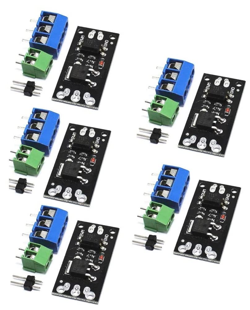
Figure 2.1: Fasizi FR120N MOS Module with included terminal blocks and pins. This image shows the complete package contents.
3. Safety Information
Please read and understand all safety instructions before using the FR120N MOS Module. Failure to follow these instructions may result in electric shock, fire, or serious injury.
- Electrical Safety: This module operates with electrical current. Always ensure power is disconnected before making any connections or disconnections.
- Voltage and Current Limits: Do not exceed the specified voltage (100V) and current (9.4A) limits of the module. Overloading can cause damage to the module and connected devices.
- Proper Wiring: Ensure all wiring is correct and secure. Loose connections can lead to overheating or malfunction.
- Heat Dissipation: For high current applications, ensure adequate ventilation around the module to prevent overheating.
- Professional Installation: If you are unsure about any aspect of installation or operation, consult a qualified electrician or electronics professional.
- Environmental Conditions: Do not expose the module to moisture, extreme temperatures, or corrosive environments.
4. Module Components and Pinout
The FR120N module features clearly labeled connection points for easy integration. Understanding these labels is crucial for proper setup.

Figure 4.1: Top view of the FR120N module with terminal blocks. Labels for PWM, GND, and LOAD are visible.

Figure 4.2: Top and bottom views of the FR120N module, illustrating the compact design and connection points.
Pinout Description:
- PWM (Control Signal Input): This pin receives the control signal from your microcontroller (e.g., Arduino). It can be a digital HIGH/LOW signal for ON/OFF control or a PWM signal for speed/intensity adjustment.
- GND (Ground): This is the common ground connection for the control signal. It must be connected to the ground of your microcontroller.
- LOAD (+) (Load Positive): Connect the positive terminal of your high-power load (e.g., motor, LED strip, solenoid) to this terminal.
- LOAD (-) (Load Negative): Connect the negative terminal of your high-power load to this terminal. This is the switched ground connection.
The module also features two 2mm diameter screw holes with an 8mm spacing for mounting purposes.
5. Setup and Wiring
Proper wiring is critical for the safe and correct operation of the FR120N module. Always ensure power is off before making any connections.
General Wiring Diagram (Conceptual):
The FR120N acts as a low-side switch. This means it switches the ground connection of the load. The positive side of the load is directly connected to the positive power supply.
- Connect the GND pin of the FR120N module to the GND of your microcontroller (e.g., Arduino).
- Connect the PWM pin of the FR120N module to a digital output pin of your microcontroller.
- Connect the positive (+) terminal of your high-power load directly to the positive (+) terminal of your load's power supply.
- Connect the negative (-) terminal of your high-power load to the LOAD (+) terminal on the FR120N module.
- Connect the LOAD (-) terminal on the FR120N module to the negative (-) terminal of your load's power supply.
Note: The module provides decoupled isolation, meaning the control signal ground and the load power ground are internally isolated to prevent interference. However, for basic operation, a common ground between the microcontroller and the load power supply is often used for simplicity, especially if the load power supply is derived from the same source as the microcontroller. For critical applications, consult specific circuit diagrams.

Figure 5.1: Bottom view of the FR120N module, showing solder pads and component layout.
6. Operating Instructions
The FR120N module can be controlled using a digital signal from a microcontroller.
ON/OFF Control (High-Level Start, Low-Level Stop):
- To turn the load ON, send a HIGH logic level (e.g., 3V or 5V) to the PWM input pin.
- To turn the load OFF, send a LOW logic level (e.g., 0V) to the PWM input pin.
This method is suitable for simple switching applications where the load needs to be either fully on or fully off.
PWM Speed/Intensity Adjustment:
For applications requiring variable control (e.g., motor speed control, LED brightness), use a Pulse Width Modulation (PWM) signal.
- Generate a PWM signal from your microcontroller and connect it to the PWM input pin of the FR120N module.
- By varying the duty cycle of the PWM signal (the ratio of ON time to the total period), you can control the average power delivered to the load.
- A higher duty cycle will result in more power (e.g., faster motor speed, brighter LED), while a lower duty cycle will result in less power.
Consult your microcontroller's documentation for details on generating PWM signals.
7. Maintenance
The FR120N MOS Module is designed for reliable operation with minimal maintenance. Follow these guidelines to ensure its longevity:
- Cleaning: Keep the module free from dust and debris. If cleaning is necessary, use a soft, dry brush or compressed air. Do not use liquid cleaners.
- Inspection: Periodically inspect all connections to ensure they are secure and free from corrosion.
- Storage: Store the module in a dry, cool environment, away from direct sunlight and extreme temperatures.
- Avoid Physical Stress: Do not apply excessive force to the module or its connections.
8. Troubleshooting
If you encounter issues with your FR120N module, consider the following common troubleshooting steps:
- Module Not Switching:
- Check all wiring connections for correctness and security.
- Verify that the control signal (PWM pin) is receiving the expected HIGH/LOW or PWM signal from your microcontroller.
- Ensure the load's power supply is connected and providing the correct voltage.
- Confirm that the load itself is functional.
- Load Not Receiving Full Power / Incorrect Speed:
- If using PWM, check the duty cycle of your PWM signal. A lower duty cycle will result in less power.
- Ensure the load's power supply can provide sufficient current for the load.
- Check for voltage drops across connections or the module itself under load.
- Module Overheating:
- Verify that the load current does not exceed the module's 9.4A rating.
- Ensure adequate ventilation around the module, especially for continuous high-current operation.
- Check for short circuits in the load or wiring.
9. Specifications
| Parameter | Value |
|---|---|
| Brand | Fasizi |
| Model | FR120N |
| Manufacturer Part Number | ELA1987 |
| Maximum Voltage | 100 Volts |
| Maximum Current | 9.4 Amperes |
| Control Signal Voltage | 3V or 5V (compatible) |
| Module Dimensions | 23mm x 16mm (approx.) |
| Screw Hole Diameter | 2mm |
| Screw Hole Spacing | 8mm |
| Material Type | Plastic |
| Color | Black |
| Country of Origin | China |
| UPC / GTIN | 798339963409 |
10. Warranty and Support
Information regarding specific warranty terms or dedicated customer support for the Fasizi FR120N MOS Module is not provided in the product data. For any issues or inquiries, please refer to your point of purchase or the manufacturer's general support channels if available.