1. Introduction
The CNCTOPBAOS DDCS Expert is a versatile 3-5 axis motion controller designed for open or closed-loop stepper and servo systems. It features a 7-inch full-color display screen with a resolution of 1024x600 and 40 operation keys. Built on an ARM+FPGA design framework, the ARM handles the human-computer interface and code analysis, while the FPGA provides underlying algorithms and control pulses, ensuring reliable and easy operation. The internal operating system is Linux-based. This controller is compatible with standard G-code and popular CAD/CAM software like ArtCam, MasterCam, ProE, JDSoft SurfMill, Aspire, and Fusion 360. It supports multiple spindle modes, including straight, gantry, and disk type tool magazines, and offers advanced features like backlash compensation and processing path preview.
Video 1.1: Introduction to DDCS-Expert Controller. This video provides an overview of the DDCS-Expert controller's features and capabilities.
2. Package Contents
Verify that all items listed below are included in your package:
- 1 x 5 Axis CNC Offline Standalone Motion Controller DDCS-EXPERT
- 1 x 4GB USB Flash Drive
- 1 x M3K Extended Keyboard
- 1 x Matching Cable for M3K Keyboard
- 1 x USB Extension Cable
- 1 x Network Cable
- 2 x 75W 24V DC Power Supply
- 1 x 5 Axis MPG Pendant Handwheel with E-Stop

Figure 2.1: Overview of the CNCTOPBAOS DDCS Expert Kit components, including the controller, keyboard, handwheel, and power supplies.
3. Setup and Installation
3.1 Controller Overview and Connections
Familiarize yourself with the main controller unit and its various input/output ports.
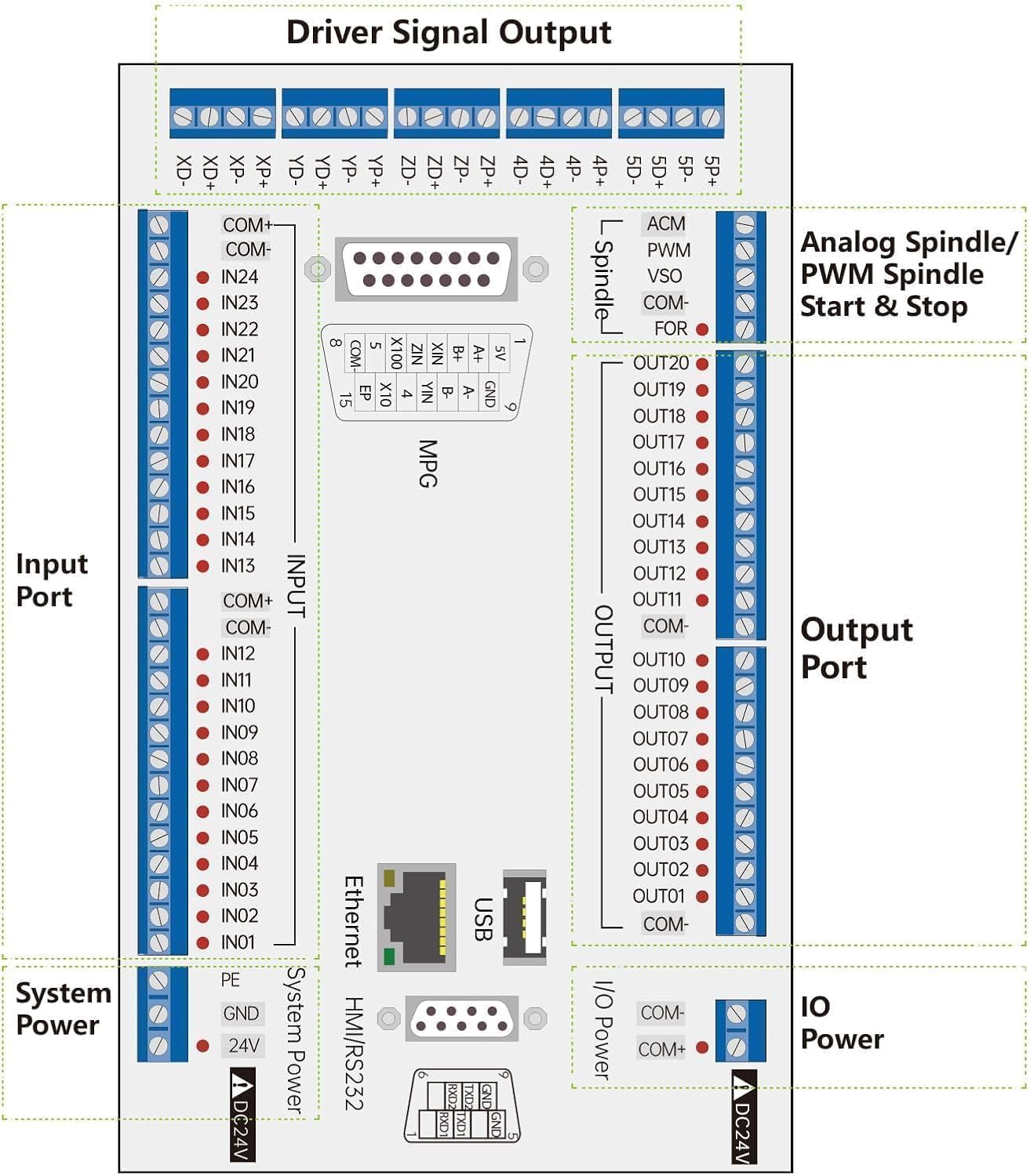
Figure 3.1: Detailed layout of the DDCS Expert controller board, highlighting driver signal output, input ports, output ports, analog spindle/PWM spindle start & stop, system power, and IO power connections.
3.2 Power Supply Wiring
Connect the 24V DC power supplies to the controller. Ensure correct polarity and secure connections. The system requires two 75W 24V DC power supplies.

Figure 3.2: Wiring diagram for the 75W 24V DC power supply, showing connections for live wire, negative wire, ground wire, and DC power output.

Figure 3.3: Illustration of connecting the power supply to the controller, including an optional EMI filter for stable operation.
3.3 MPG Handwheel Connection
The MPG pendant handwheel provides manual pulse generation for precise axis control. Connect it to the designated MPG port on the controller.

Figure 3.4: The MPG handwheel connected to the DDCS Expert controller board.

Figure 3.5: Detailed wiring diagram for the MPG handwheel, showing pin assignments and connections.
3.4 M3K Extended Keyboard Connection
Connect the M3K extended keyboard to the controller using the provided matching cable. This keyboard offers additional operational keys for enhanced control.

Figure 3.6: The M3K extended keyboard, providing additional control inputs for the DDCS Expert system.

Figure 3.7: Notes regarding the connection and power supply for the M3K extended keyboard via the serial port.
3.5 Limit Switch and Probe Wiring
Properly wire limit switches and probes to the input ports of the controller for safe and accurate operation. The controller supports both floating and fixed probes.

Figure 3.8: Wiring diagram for proximity switches (S1, S2) and a mechanical switch (S3) for limit detection, along with probe connection.

Figure 3.9: Wiring diagram for a tool setter probe, connecting to the input ports of the controller.
Video 3.1: DDCSV Limit Signal Function Display. This video demonstrates the functionality and setup of limit signals on a DDCSV controller, which is similar to the DDCS Expert.
4. Operating Instructions
4.1 Basic Navigation and Jogging
The DDCS Expert features a user-friendly interface for manual control and program execution. Use the MPG handwheel for precise jogging of axes.
Video 4.1: Test Video of DDCSV4.1 Offline CNC Controller. This video demonstrates basic jogging and control using the MPG handwheel with a DDCSV4.1 controller.
Video 4.2: Test Video of DDCSV3.1 Offline CNC Controller. This video illustrates manual control and jogging operations using the MPG handwheel on a DDCSV3.1 controller.
4.2 Homing Function
The homing function is crucial for establishing the machine's reference point. Ensure limit switches are correctly configured for accurate homing.
Video 4.3: DDCS-Expert Homing Signal Display. This video demonstrates the homing procedure and signal display on the DDCS-Expert controller.
Video 4.4: DDCSV3.1 Homing Function Display. This video shows the homing function in action on a DDCSV3.1 controller, illustrating the process of returning axes to their home positions.
4.3 Loading and Running G-Code
The controller supports loading G-code files from a USB flash drive. The system can preview the processing path before machining, enhancing operational safety and precision.

Figure 4.1: The main interface of the DDCS Expert controller, showing G-code loading and execution options.
5. Maintenance
- Regular Cleaning: Keep the controller and all connected components free from dust and debris. Use a soft, dry cloth for cleaning.
- Cable Inspection: Periodically check all cables for wear, damage, or loose connections. Replace any damaged cables immediately.
- Software Updates: Ensure your controller's firmware is up-to-date. Refer to the manufacturer's website for the latest versions and update instructions.
- Environmental Conditions: Operate the controller within recommended temperature and humidity ranges to prevent damage.
6. Troubleshooting
- Controller Not Powering On: Verify that the 24V DC power supplies are correctly connected and providing power. Check all power cables and connections.
- Axes Not Moving: Ensure all motor wiring is correct and secure. Check motor parameters in the controller settings. Verify that limit switches are not triggered, causing an alarm state.
- Keyboard Not Responding: Confirm the M3K keyboard cable is securely connected. Check the keyboard settings within the controller's parameters.
- Incorrect Unit Display (mm/inch): The controller supports both mm and inch units. The default is mm. To use inches, set it to imperial units via G20 code in your program. Refer to the manual for specific parameter adjustments if needed.
- Program Errors/Glitches: Ensure G-code is correctly formatted and compatible with the controller. Check for software alarms displayed on the screen.
7. Specifications
| Feature | Detail |
|---|---|
| Max. Axes Supported | 5 Axis |
| Output Frequency per Axis | 1MHz (1000KHz) |
| Display Screen | 7 inch Full Color Display (1024x600 resolution) |
| Operation Keys | 40 keys |
| Digital Inputs | 24 photoelectric isolated |
| Digital Outputs | 21 photoelectric isolated |
| Spindle Control | 0-10V Analog, also supports PWM Output |
| Compatible Software | ArtCam, MasterCam, ProE, JDSoft SurfMill, Aspire, Fusion 360, etc. |
| Operating System | Linux-based |
| Power Supply for Controller | 24VDC, minimum 0.5A |
| Power Supply for IO Port | 24VDC, minimum 0.5A (system supplies power to IO ports) |
| Unit Support | mm and inch (default mm, G20 for imperial) |
| Item Weight | 8.84 pounds |
| Package Dimensions | 12.95 x 10.83 x 9.33 inches |
8. Warranty and Support
For warranty information and technical support, please refer to the documentation provided with your purchase or contact CNCTOPBAOS customer service directly. Keep your purchase receipt for warranty claims.
9. Safety Information
- Always disconnect power before performing any wiring or maintenance.
- Ensure proper grounding for all electrical components.
- Use appropriate personal protective equipment (PPE) when operating CNC machinery.
- Familiarize yourself with the emergency stop procedures and ensure the E-Stop button is easily accessible.
- Do not operate the controller or connected machinery if any components are damaged or malfunctioning.
- Keep children and unauthorized personnel away from the operating area.