Introduction
This instruction manual provides detailed guidance for the assembly, operation, and maintenance of your Whadda WSAH1803 Universal Mono Preamplifier Soldering Kit. This kit is designed to introduce users to basic electronics and soldering techniques while building a functional mono preamplifier. Please read all instructions carefully before beginning assembly.
Safety Instructions
- Always work in a well-ventilated area to avoid inhaling solder fumes.
- Use appropriate eye protection (safety glasses) when soldering.
- Ensure your soldering iron is placed in a safe stand when not in use and is unplugged when finished.
- Avoid touching the hot tip of the soldering iron or freshly soldered joints.
- Keep all components and tools out of reach of children and pets.
- Verify correct component orientation (e.g., electrolytic capacitors, diodes, ICs) before soldering to prevent damage.
- Use a suitable power supply (12V DC) and ensure correct polarity when connecting power to the assembled circuit.
Package Contents
Carefully unpack the kit and verify that all components listed below are present. If any parts are missing or damaged, please contact Whadda customer support.
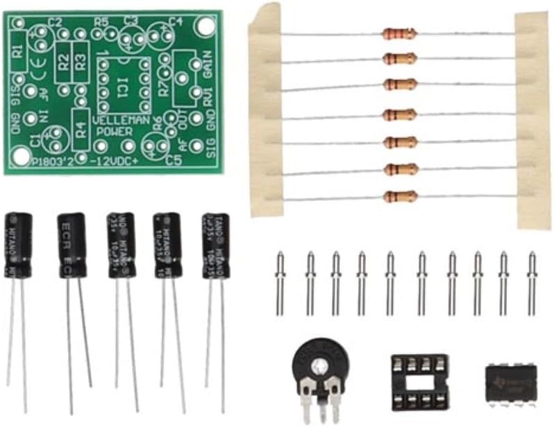
Image: All components of the Whadda WSAH1803 Universal Mono Preamplifier Soldering Kit laid out, including the PCB, resistors, capacitors, IC, IC socket, potentiometer, and pin headers.
- Printed Circuit Board (PCB)
- Resistors (various values)
- Electrolytic Capacitors
- Ceramic Capacitors
- Integrated Circuit (IC)
- IC Socket
- Potentiometer (for gain control)
- Pin Headers / Connectors
Setup: Assembly Instructions
Follow these steps to assemble your Whadda WSAH1803 preamplifier kit. It is recommended to solder components from smallest to largest.
- Component Identification: Before soldering, identify all components by their markings and match them to the corresponding positions on the PCB. Resistors are identified by color codes, capacitors by capacitance and voltage, and the IC socket and IC by their pin counts and notch/dot for orientation.
- Solder Resistors: Insert the resistors into their designated spots on the PCB. Bend the leads slightly on the solder side to hold them in place. Solder each lead and trim the excess.
- Solder Ceramic Capacitors: Insert the small, non-polarized ceramic capacitors. Solder and trim leads.
- Solder IC Socket: Place the IC socket onto the PCB, ensuring the notch on the socket aligns with the notch marking on the PCB silkscreen. Solder all pins.
- Solder Electrolytic Capacitors: These are polarized. Ensure the longer lead (positive) goes into the '+' marked hole or the square pad, and the shorter lead (negative) aligns with the '-' marking or round pad. Solder and trim leads.
- Solder Potentiometer and Pin Headers: Solder the potentiometer and any pin headers or connectors according to the PCB markings.
- Insert IC: Carefully insert the Integrated Circuit (IC) into its socket. Ensure the notch on the IC aligns with the notch on the socket and PCB. Apply gentle, even pressure until it is fully seated. Do not solder the IC directly unless specified; use the socket.

Image: A partially assembled Whadda WSAH1803 preamplifier circuit board, showing resistors and some capacitors already soldered in place.
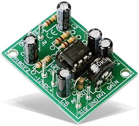
Image: A fully assembled Whadda WSAH1803 Universal Mono Preamplifier circuit board, with all components soldered and the IC inserted into its socket.
Operating Instructions
Once assembled, follow these steps to operate your mono preamplifier:
- Power Connection: Connect a stable 12V DC power supply to the designated power input terminals (usually marked +12V and GND). Ensure correct polarity to prevent damage to the circuit.
- Audio Input: Connect your audio source (e.g., microphone, low-level audio device) to the audio input terminals (usually marked 'AF IN' or 'SIG IN' and 'GND'). This preamplifier is designed for mono signals.
- Audio Output: Connect the preamplifier's output terminals (usually marked 'AF OUT' or 'SIG OUT' and 'GND') to an amplifier or active speaker system.
- Gain Adjustment: Use the onboard potentiometer (often labeled 'GAIN' or 'RV1') to adjust the amplification level of the audio signal. Start with the gain at its lowest setting and gradually increase it to avoid distortion.
- Testing: Play an audio signal through your source and listen to the output. Adjust the gain as needed for optimal sound.
Maintenance
The Whadda WSAH1803 preamplifier kit requires minimal maintenance. Follow these guidelines to ensure longevity:
- Cleaning: Keep the circuit board clean and free from dust and debris. Use a soft, dry brush or compressed air for cleaning. Avoid using liquids.
- Storage: Store the assembled preamplifier in a dry, cool environment, away from direct sunlight and extreme temperatures.
- Inspections: Periodically inspect solder joints for any signs of cracking or corrosion. Re-solder if necessary.
- Power Supply: Always use a regulated 12V DC power supply to prevent damage from voltage fluctuations.
Troubleshooting
If you encounter issues with your preamplifier, refer to the following troubleshooting tips:
| Problem | Possible Cause | Solution |
|---|---|---|
| No sound output |
|
|
| Distorted or weak sound |
|
|
| Humming or buzzing noise |
|
|
Specifications
- Model: WSAH1803
- Brand: Whadda
- Input Voltage: 12 Volts DC
- Number of Channels: 1 (Mono)
- Dimensions (L x W x H): Approximately 3.8 x 7.8 x 15.5 cm (assembled board)
- Weight: Approximately 32 grams
- Certification: CE
- Components Included: PCB, Resistors, Capacitors, IC, IC Socket, Potentiometer, Pin Headers
Warranty and Support
Whadda products are manufactured by Velleman Group nv. For any questions, technical assistance, or warranty claims, please refer to the official Whadda or Velleman Group website for contact information and support resources. Please note that as a soldering kit, the warranty may cover components but typically not issues arising from incorrect assembly or soldering errors.
Official Whadda Website: https://www.velleman.eu/products/view/?id=461802