Consolidated 19900-1-CC-MS-31
19900-1-CC-MS-31 FLANGED Relief Valve
User Manual
Introduction
This manual provides essential information for the safe and effective installation, operation, and maintenance of the Consolidated 19900-1-CC-MS-31 Flanged Relief Valve. This valve is designed to protect pressure vessels and other equipment from overpressure by automatically releasing fluid when the set pressure is exceeded. It features a 1-inch flanged connection and a set pressure of 150 PSI.

Figure 1: General view of the Consolidated 19900-1-CC-MS-31 Flanged Relief Valve. This image shows the valve body with two flanged connections, one for inlet and one for outlet, and the hexagonal cap on top.
Safety Information
Always adhere to local safety regulations and industry best practices when handling, installing, or maintaining pressure relief devices. Failure to do so can result in serious injury, property damage, or death.
- Ensure the system is depressurized and isolated before any installation or maintenance work.
- Wear appropriate Personal Protective Equipment (PPE), including safety glasses, gloves, and protective clothing.
- Do not tamper with the factory-set pressure. Any adjustments must be performed by qualified personnel using calibrated equipment.
- Verify that the valve's specifications (pressure, temperature, material compatibility) match the system requirements.
Setup and Installation
Proper installation is critical for the reliable operation of the relief valve. Follow these steps carefully:
- Inspection: Before installation, visually inspect the valve for any signs of damage during shipping. Ensure all protective caps are removed from the flanged connections.
- Mounting Orientation: Install the valve in the correct orientation as indicated by flow arrows (if present) or manufacturer guidelines. For this flanged relief valve, ensure the inlet flange is connected to the pressure source and the outlet flange is connected to the discharge system.
- Flange Connection: Use appropriate gaskets and bolts for the 1-inch flanged connections. Ensure flange faces are clean and free of debris. Tighten bolts evenly in a star pattern to prevent leaks and ensure proper sealing.
- Support: Provide adequate support for the valve and associated piping to prevent undue stress on the connections.
- Discharge Piping: Ensure the discharge piping is adequately sized and routed to a safe location, free from obstructions, to handle the full relief capacity without backpressure issues.

Figure 2: Angled view of the relief valve, showing the robust construction and flanged connections. This perspective highlights the inlet and outlet flanges, which are crucial for secure installation.

Figure 3: Close-up view of the flanged ends of the relief valve, with protective caps still in place. These caps protect the sealing surfaces during transport and should be removed prior to installation.
Operating Principles
The Consolidated 19900-1-CC-MS-31 is a spring-loaded relief valve designed to open automatically when the upstream pressure reaches its factory-set point of 150 PSI. Once the pressure drops below the set point (typically with a blowdown differential), the valve will re-seat, preventing further fluid release. This automatic operation ensures system integrity and prevents overpressure conditions.
Regular monitoring of system pressure is recommended to ensure the valve is operating within its intended parameters. The valve is a safety device and should not be used for process control.
Maintenance
Routine maintenance is essential to ensure the long-term reliability and performance of the relief valve. Maintenance should only be performed by qualified personnel.
- Visual Inspection: Periodically inspect the valve for external corrosion, leaks, or damage to the flanges and body.
- Leak Checks: Check for any signs of leakage around the flange connections or the valve body.
- Functionality Test: Depending on application and regulatory requirements, periodic testing (e.g., pop testing) may be necessary to verify the valve opens at its set pressure. This must be done by certified technicians.
- Cleaning: Keep the exterior of the valve clean. Do not use harsh chemicals that could damage the valve material.
- Recalibration: Relief valves should be recalibrated and serviced at regular intervals as per industry standards or manufacturer recommendations to ensure accurate set pressure and proper sealing.
Troubleshooting
This section outlines common issues and potential solutions for the relief valve. For complex problems, contact qualified service personnel.
| Problem | Possible Cause | Solution |
|---|---|---|
| Valve leaking at flange connection | Improper bolt tightening, damaged gasket, dirty flange face. | Re-tighten bolts evenly, replace gasket, clean flange faces. Ensure system is depressurized first. |
| Valve not opening at set pressure | Valve seized due to corrosion/debris, incorrect set pressure, spring fatigue. | Do not attempt to force open. Contact certified technician for inspection, cleaning, or recalibration. |
| Valve weeping/chattering | Seat damage, foreign material on seat, excessive backpressure, incorrect blowdown. | Contact certified technician for inspection and repair. Check discharge piping for obstructions. |
Specifications
Key specifications for the Consolidated 19900-1-CC-MS-31 Flanged Relief Valve:
- Model: 19900-1-CC-MS-31
- Brand: Consolidated
- Mounting Type: Flanged
- Set Pressure: 150 PSI
- Size: 1 IN
- Product Dimensions (L x W x H): 16.5 x 10 x 7.75 inches
- Weight: Approximately 16.65 Pounds
- Outlet Connection Type: Flange
- Specification Met: ms 31
- Manufacturer: CONSOLIDATED
- ASIN: B09XXXXMCC

Figure 4: Detailed view of the valve's nameplate, showing critical information such as model number, serial number, set pressure, and manufacturer details. This label is essential for identification and compliance.
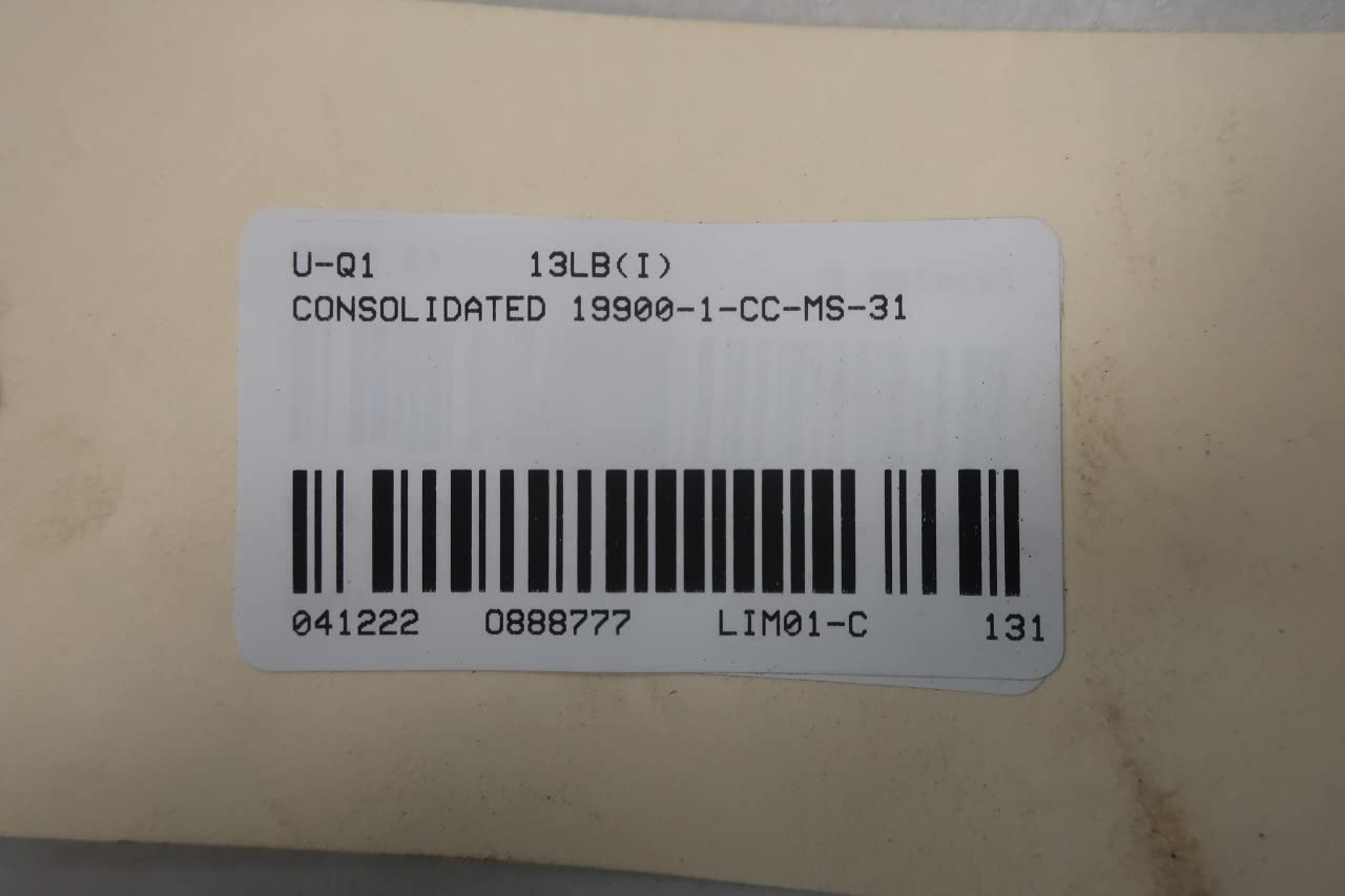
Figure 5: Barcode label for the Consolidated 19900-1-CC-MS-31, typically found on packaging or the product itself for inventory and tracking purposes. It includes the model number and other identifiers.
Warranty and Support
Consolidated products are manufactured to high standards. For specific warranty terms and conditions, please refer to the documentation provided with your purchase or contact Consolidated directly. For technical support, service, or parts inquiries, please reach out to the manufacturer or an authorized distributor.
Manufacturer: CONSOLIDATED
Note: Always provide the model number (19900-1-CC-MS-31) and ASIN (B09XXXXMCC) when contacting support for efficient assistance.
Ask a question about this manual
Ask about setup, troubleshooting, compatibility, parts, safety, or missing instructions. Manuals+ will review the question and use this page’s manual context to help answer it.