1. Safety Instructions
Always prioritize safety when operating welding equipment. Failure to follow safety precautions can result in serious injury or death.
- Wear appropriate personal protective equipment (PPE), including a welding helmet with proper shade, flame-resistant clothing, welding gloves, and safety shoes.
- Ensure adequate ventilation to avoid inhaling welding fumes.
- Keep a fire extinguisher nearby.
- Do not operate the welder in damp or wet conditions.
- Ensure the workpiece is properly grounded.
- Disconnect power before performing any maintenance or changing accessories.
- Avoid touching live electrical parts or hot metal.
2. Product Overview
The H HZXVOGEN MIG250 is a versatile 6-in-1 multi-process welding machine designed for various welding tasks. It supports Gas MIG, Gasless Flux Core MIG, MMA (Stick), Spot welding, and Lift TIG. It is compatible with both 110V and 220V power inputs and features synergic control for ease of use.


3. Package Contents
Verify that all items listed below are included in your package:
- MIG250 Welding Machine
- MIG Torch
- Ground Clamp
- Electrode Holder (for MMA)
- 0.8mm Welding Wire
- Wire Wheel
- Conductive Nozzle
- Graphene Tube
- Demolition Wrench
- Hose Clamp
- User Manual

4. Setup
4.1 Power Connection
The MIG250 welder is designed for dual voltage input (110V/220V). The machine automatically detects the input voltage.
- Connect the power cord to a suitable power outlet. Ensure the outlet matches the welder's voltage requirements.
- Turn the power switch on the rear panel to the 'ON' position.
4.2 Welding Mode Connections
The welder supports multiple processes. Connect the accessories according to the desired welding mode.

4.2.1 MMA (Stick) Welding Setup
- Connect the electrode holder cable to the positive (+) terminal.
- Connect the ground clamp cable to the negative (-) terminal.
- Securely attach the ground clamp to the workpiece.
- Insert the welding electrode into the electrode holder.
4.2.2 MIG Welding Setup (Gas/Flux Core)
- Wire Spool Installation: Open the side panel. Install the appropriate welding wire spool onto the spindle. Secure it with the knob.
- Wire Feeding: Guide the wire through the wire feeder mechanism. Close the wire feeder tension arm.
- MIG Torch Connection: Connect the MIG torch to the Euro connector on the front panel.
- Ground Clamp: For Gas MIG, connect the ground clamp to the negative (-) terminal. For Gasless Flux Core MIG, connect the ground clamp to the positive (+) terminal.
- Gas Connection (for Gas MIG): Connect the gas hose from your gas cylinder (e.g., CO2, Argon, or mixed gas) to the gas inlet on the rear panel of the welder. Ensure all connections are tight to prevent gas leaks.

4.2.3 Lift TIG Welding Setup
- Connect the Lift TIG torch (WP17V TIG torch sold separately) to the negative (-) terminal.
- Connect the ground clamp cable to the positive (+) terminal.
- Connect the gas hose from your Argon gas cylinder to the gas inlet on the rear panel.
5. Operating Instructions
5.1 Control Panel Overview
The MIG250 features a large LED digital display and intuitive controls for easy operation.

5.2 Mode Selection
Use the 'MODE' button to cycle through the available welding processes: Gas MIG, Gasless Flux Core MIG, MMA, Spot, and Lift TIG.
5.3 Parameter Adjustment
Adjust welding parameters using the dedicated knobs and buttons on the control panel.
- Current Knob: Adjusts the welding current (Amps).
- Voltage Knob: Adjusts the welding voltage (Volts).
- Wire Button: Selects the wire diameter (e.g., 0.6mm, 0.8mm, 0.9mm, 1.0mm).
- Material Button: Selects the material type (e.g., Fe+CO2, Fe+MIX, Flux, CrNi, AlMg).
- Burn Back Adjustment: Adjusts the burn-back time to prevent wire sticking.
- Pre-flow/Post-flow: Adjusts gas pre-flow and post-flow times for TIG welding.
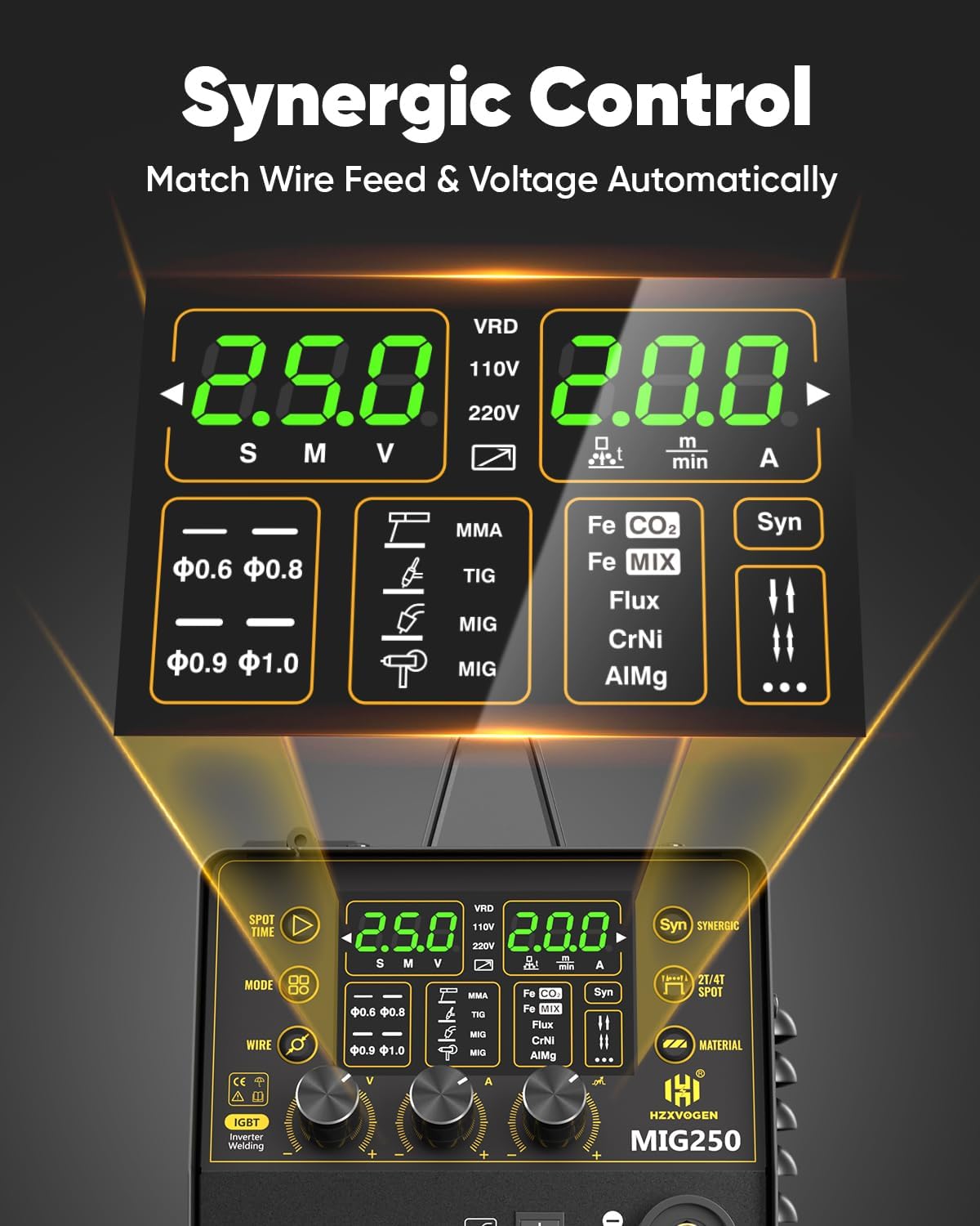
5.4 Synergic Mode
The synergic MIG technology simplifies welding by automatically adjusting recommended current and wire feed speed based on your wire diameter and material selection. This mode is ideal for beginners.
5.5 2T/4T Function
The 2T/4T function allows for different torch trigger operations:
- 2T (Two-Touch): Press and hold the trigger to weld, release to stop.
- 4T (Four-Touch): Press and release the trigger to start welding, press and release again to stop. This is useful for longer welds.
5.6 Spot Welding Function
The Spot welding function allows for precise, timed spot welds. Adjust the spot time (0-3s) by rotating the current button.
6. Maintenance
6.1 General Cleaning
Regularly clean the welder to ensure optimal performance and longevity.
- Use compressed air to blow out dust and debris from the cooling vents.
- Wipe down the exterior with a clean, dry cloth.
6.2 Wire Feeder Maintenance
Inspect the wire feeder rollers and liner regularly for wear or damage. Replace as needed to ensure smooth wire feeding.
6.3 Consumables Replacement
Regularly check and replace worn MIG tips, nozzles, and TIG electrodes to maintain weld quality.
7. Troubleshooting
If you encounter issues, refer to the following common problems and solutions:
| Problem | Possible Cause | Solution |
|---|---|---|
| No arc/Poor arc starting | Improper grounding, incorrect settings, worn consumables | Check ground clamp connection, verify settings, replace contact tip/electrode. |
| Wire feeding issues | Incorrect roller size, worn liner, wire tangle | Ensure correct drive roller, replace liner, untangle wire spool. |
| Overheating protection activated | Extended use, blocked vents | Allow machine to cool down, ensure clear airflow to vents. |
| Poor weld quality | Incorrect parameters, improper technique, contaminated material | Adjust current/voltage/wire feed speed, clean workpiece, improve technique. |
8. Specifications
Below are the technical specifications for the H HZXVOGEN MIG250 welder:
| Feature | Specification |
|---|---|
| Model | MIG250 |
| Input Voltage | 110/220V |
| Welding Processes | Gas MIG, Flux Core MIG, MMA, Spot, Lift TIG |
| Max Output Current | 200A |
| Item Weight | 12.7 kg |
| Dimensions | 49.2 x 45.2 x 26.8 cm |
| Cooling | Energy-efficient cooling fan |
| Protection Features | VRD, Over Current, Over Voltage, Over-load, Overheating |
8.1 MIG Welding Parameters

8.2 Stick & Lift TIG Welding Parameters

9. Warranty and Support
The HZXVOGEN MIG250 welder comes with a 2-year quality support warranty. For any technical assistance, warranty claims, or product inquiries, please contact H HZXVOGEN customer service.
You can visit the official H HZXVOGEN store for more information and support: H HZXVOGEN Store