1. Product Overview
The Qiulaofu 433MHz Wireless 2-Channel AC Relay Receiver Smart Switch is designed for remote control of various AC electrical devices. This intelligent switch allows you to control two independent electrical devices simultaneously, such as lights, fans, or motors for curtains, roller shutters, blinds, garage doors, and gates. It operates on AC 90V-250V and features a 10A relay with a recommended load of less than 5A or 500W for optimal performance. The RF technology ensures stable signal transmission, capable of passing through walls, floors, and doors, with a maximum range of up to 328ft (100m) in open areas.

Image 1.1: Various applications for the Qiulaofu Smart Switch, including garage doors, curtains, lighting, and electric gates.
2. Safety Information
- Always disconnect power before installation or maintenance to prevent electric shock.
- Ensure all wiring is performed by a qualified electrician or in accordance with local electrical codes.
- Do not exceed the maximum load capacity of 10A (recommended less than 5A or 500W) to avoid damage to the device or connected appliances.
- Keep the device away from water and high humidity environments.
- Replace remote control batteries promptly when voltage is low to maintain strong signal transmission.
3. Product Components
The package typically includes the 2-channel relay receiver module and one or more remote controls. The receiver features a learning button for programming and screw terminals for wiring connections.

Image 3.1: The wireless receiver module and remote control, showing the learning button on the receiver.

Image 3.2: Remote control dimensions and battery information (23A/12V battery).
4. Specifications
| Brand | Qiulaofu |
| Model Number | 2202-10A |
| Input Voltage | AC 90V-250V |
| Output Voltage | Equal to input voltage |
| Max Load Current | 10 Amps (Recommended < 5 Amps) |
| Max Load Power | Recommended < 500W |
| RF Frequency | 433MHz |
| Transmission Distance | Up to 328ft (100m) in open areas |
| Operating Modes | Momentary, Toggle, Latched (+ Stop) |
| Dimensions (Receiver) | 85mm x 43mm x 30mm (3.35in x 1.69in x 1.18in) |
| Item Weight | 5.9 ounces |
| Remote Battery Type | 23A/12V Alkaline (included) |

Image 4.1: Dimensions of the receiver module.
5. Installation and Wiring
The receiver module is designed for simple wiring without the need for wire jumpers. Ensure power is disconnected before proceeding with any wiring.
5.1 General Wiring Diagram
Connect the AC 90V-250V power supply to the "IN" terminals (L for Live, N for Neutral). Connect your electrical device(s) to the "OUT" terminals (L1, L2, N). The improved receiver can control two electrical devices simultaneously.
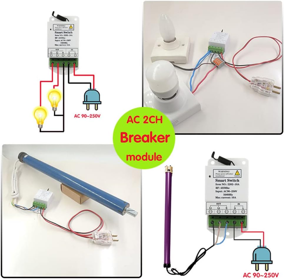
Image 5.1: General wiring diagram for connecting lights and a motor to the 2-channel receiver.
5.2 Wiring for Motor Control (e.g., Curtains, Garage Doors)
For controlling AC motors, such as those found in curtains, roller shutters, or garage doors, connect the motor's power lines to the "OUT" terminals. The receiver controls the forward and reverse rotation of the AC motor.
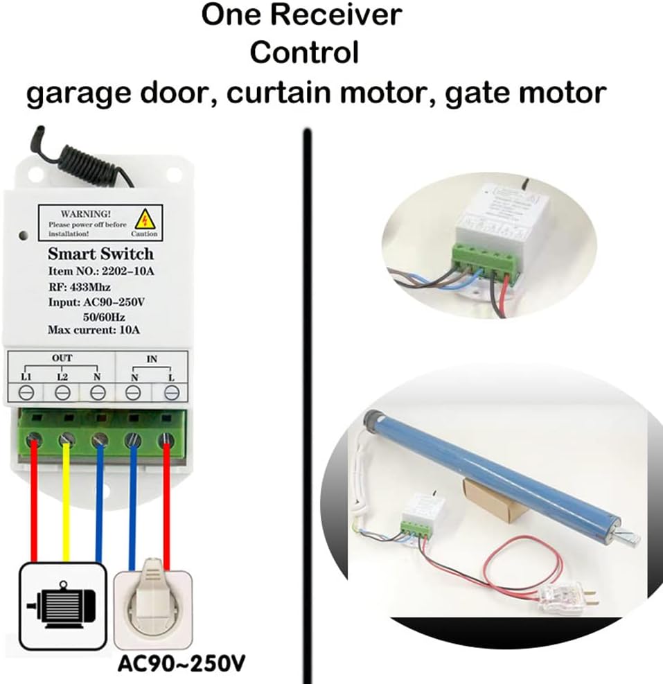
Image 5.2: Wiring for controlling a motor (e.g., for garage doors or curtains).
5.3 Wiring for Light Control
To control two lights or other electrical equipment, connect each device to the respective "OUT" terminals.
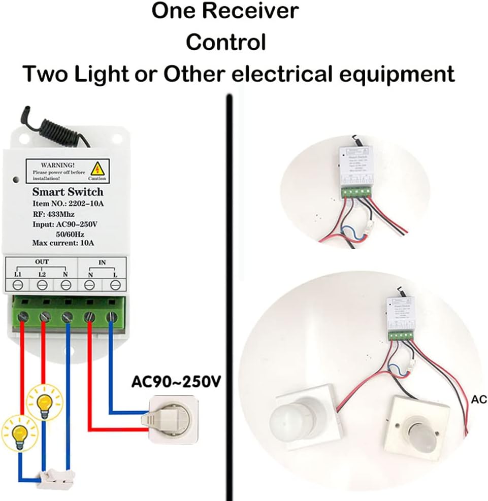
Image 5.3: Wiring for controlling two lights or other electrical equipment.
6. Operating Modes and Programming
The receiver supports Momentary, Toggle, and Latched (+ Stop) modes. The default mode is Latched (+ Stop). To change the operating mode, you must first reset the receiver and then program it with the remote control in the desired mode.
6.1 Momentary Mode
In Momentary Mode, the relay turns on only while the remote button is pressed and held. It turns off when the button is released.
Programming Momentary Mode:
- Press the learning button on the receiver 1 time. The indicator LED on the receiver will light up.
- Press button "A" on the remote control. The indicator LED on the receiver will flash several times and then turn off.
- Press button "B" on the remote control. The indicator LED on the receiver will flash several times and then turn off. Programming is complete.
6.2 Toggle Mode
In Toggle Mode, pressing a button once turns the relay on, and pressing the same button again turns it off.
Programming Toggle Mode:
- Press the learning button on the receiver 2 times. The indicator LED on the receiver will light up.
- Press button "A" on the remote control. The indicator LED on the receiver will flash several times and then turn off.
- Press button "B" on the remote control. The indicator LED on the receiver will flash several times and then turn off. Programming is complete.
6.3 Latched Mode (Default)
In Latched Mode, pressing button "A" turns relay 1 on. Pressing button "B" turns relay 2 on and simultaneously turns relay 1 off. Pressing button "C" turns both relay 1 and relay 2 off. This mode is recommended for controlling devices like curtain motors where specific actions (up, stop, down) are needed.
Programming Latched Mode:
- Press the learning button on the receiver 3 times. The indicator LED on the receiver will light up.
- Press button "A" on the remote control. The indicator LED on the receiver will flash several times and then turn off.
- Press button "B" on the remote control. The indicator LED on the receiver will flash several times and then turn off. Programming is complete.

Image 6.1: Controlling a garage door using a 3-button remote in Latched Mode (Up, Stop, Down).
6.4 Resetting the Receiver (Clearing Data)
To clear all programmed remote controls and operating modes from the receiver, perform a reset. This is necessary before changing the operating mode of a remote control.
Reset Procedure:
- Press the learning button on the receiver 9 times. The indicator LED on the receiver will flash several times and then turn off. Reset is complete.
- Note: After a reset, all previously paired remote controls will no longer work and must be reprogrammed.
7. Video Tutorial: How to Set Up Operating Modes
Watch this official video for a visual guide on how to set up the different operating modes (Momentary, Toggle, Latched) for your Qiulaofu AC Power Smart 2CH Relay Wireless Switch.
Video 7.1: A detailed video demonstrating the setup process for Momentary, Toggle, and Latched operating modes for the Qiulaofu 2-channel relay switch.
8. Troubleshooting
- Remote control not working after setup: Ensure the receiver was reset before programming a new mode. All remotes need to be reprogrammed after a reset.
- Weak signal or intermittent control:
- Replace the remote control battery if its voltage is low.
- Slightly stretch the antenna on the receiver for better signal reception.
- Ensure there are no major obstructions or sources of interference between the remote and the receiver.
- Device not responding:
- Check all wiring connections to ensure they are secure and correct.
- Verify that the power supply to the receiver is active (AC 90V-250V).
- Confirm that the connected device is within the recommended load limits (less than 5A or 500W).
- Latched mode not working as expected: Ensure the remote control has at least 3 or more buttons for proper functionality in Latched mode.
9. Customer Support
For any questions or assistance, please contact Qiulaofu customer support via email. We are committed to customer satisfaction and will patiently help you resolve any issues.
(Specific contact information may be provided by the seller.)