1. Introduction
The QCCAN XL6019 is a versatile monolithic integrated circuit designed for efficient boost and buck conversion applications. This power module operates within a DC input voltage range of 3.3V to 35V and can provide an adjustable output voltage up to 40V. It features low ripple output and incorporates a built-in power MOS, making it suitable for various electronic projects requiring stable and adjustable power supply.
Key features include a wide input voltage range, high conversion efficiency, and integrated protection circuits for enhanced reliability.

Image 1.1: Four QCCAN XL6019 5A Step-Up DC-DC Power Modules. Each module is a compact red circuit board with blue screw terminals for input and output, a blue potentiometer, and various electronic components.
2. Specifications
| Feature | Specification |
|---|---|
| Input Voltage Range | DC 3.3V - 35V |
| Output Voltage Range | Adjustable DC 5V - 40V |
| Maximum Switching Current | 5A |
| Switching Frequency | Fixed 22KHz |
| Conversion Efficiency | Over 90% |
| Output Voltage Sampling | 1.25V |
| Protection Features | Over-temperature protection, Over-current protection, SW built-in over-voltage protection |
| Dimensions (L x W x H) | Approximately 50mm x 28mm x 15mm (2.0 x 1.1 x 0.6 inches) |
| Weight | Approximately 2.08 ounces (per module) |
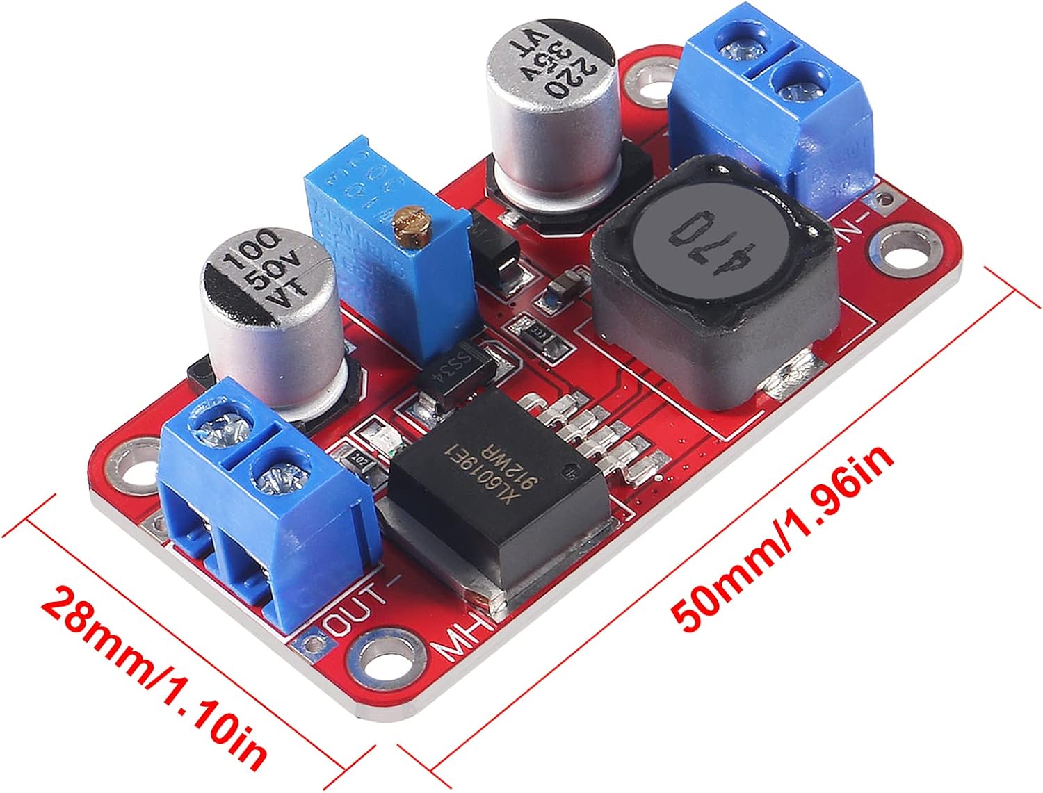
Image 2.1: The XL6019 module with its dimensions indicated as 50mm (1.96in) in length and 28mm (1.10in) in width.
3. Setup and Connection
Proper connection of the input and output terminals is crucial for the safe and correct operation of the XL6019 module. Always ensure power is disconnected before making any connections.
- Identify Terminals: Locate the 'IN+' and 'IN-' terminals for input power, and 'OUT+' and 'OUT-' terminals for output power.
- Input Power Connection: Connect your DC power source (3.3V-35V) to the 'IN+' (positive) and 'IN-' (negative) terminals. Ensure correct polarity.
- Output Load Connection: Connect your load to the 'OUT+' (positive) and 'OUT-' (negative) terminals.
- Power On: Once all connections are secure, apply power to the input terminals. The power indicator light on the module should illuminate, indicating it is operating.

Image 3.1: A detailed diagram of the XL6019 module, showing input (IN+, IN-) and output (OUT+, OUT-) terminals, the XL6019 Step-Up Chip, Inductance, Multi-coil Adjustable Potentiometer, and Red Output Indicator. It also highlights the input voltage range (3V-35V) and output voltage range (5V-40V).
4. Operating Instructions
The output voltage of the XL6019 module is adjustable via the onboard potentiometer.
- Connect Multimeter: Before connecting your final load, connect a multimeter to the 'OUT+' and 'OUT-' terminals to monitor the output voltage.
- Adjust Output Voltage: Carefully turn the blue potentiometer knob.
- Turning the knob counter-clockwise will generally boost the output voltage.
- Turning the knob clockwise will generally buck (decrease) the output voltage.
- Verify Stability: Once the desired voltage is set, you may connect your load. It is recommended to re-verify the output voltage under load conditions, especially for sensitive applications.
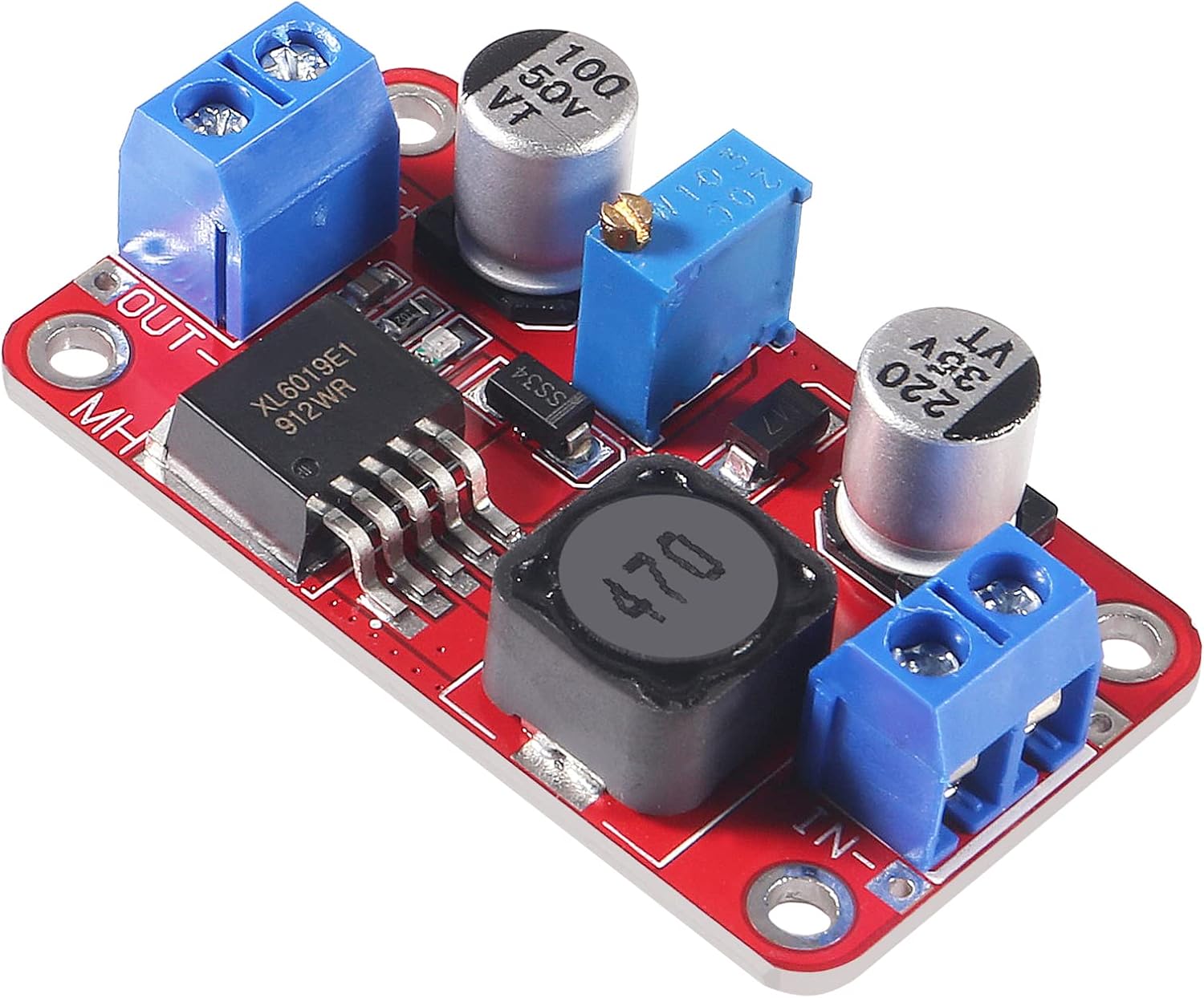
Image 4.1: A close-up view of the blue multi-turn potentiometer used for adjusting the output voltage on the XL6019 module.
5. Important Notes and Safety Precautions
- Correct Connections: Always ensure that input and output connections are made with correct polarity. Incorrect connections can damage the module and connected devices.
- Minimum Differential Voltage: As this is a boosting module, maintain a minimum 1.5V differential between the input and output voltages to ensure stable output.
- Heat Dissipation: For continuous operation at high currents (above 2.5A) or output power exceeding 10W, it is strongly recommended to add an external heat sink to the module to prevent overheating and ensure long-term reliability.
- Environmental Conditions: Operate the module in a dry, well-ventilated environment, away from moisture, dust, and extreme temperatures.
- Insulation: Ensure proper insulation to prevent accidental short circuits, especially when integrating the module into larger systems.
6. Maintenance
The XL6019 power module is designed for reliable operation with minimal maintenance. However, adhering to the following guidelines can prolong its lifespan:
- Keep Clean: Periodically inspect the module for dust or debris accumulation. Use a soft, dry brush or compressed air to gently clean the components.
- Inspect Connections: Regularly check all input and output wire connections to ensure they are secure and free from corrosion. Loose connections can lead to unstable operation or damage.
- Environmental Control: Ensure the operating environment remains within specified temperature and humidity ranges to prevent component degradation.
7. Troubleshooting
- No Output Voltage:
- Verify input power is applied and within the specified range (3.3V-35V).
- Check input and output polarity for correct connection.
- Ensure the power indicator LED is illuminated. If not, check input power source.
- Rotate the potentiometer through its full range to see if voltage appears.
- Incorrect Output Voltage:
- Use a multimeter to accurately measure the output voltage.
- Adjust the potentiometer slowly to reach the desired voltage.
- Ensure the input voltage is sufficient and stable.
- Module Overheating:
- Reduce the load current or output power.
- Ensure adequate ventilation around the module.
- Consider adding a heat sink, especially for continuous high-power operation (above 10W output).
- Verify that the input-output differential voltage is not excessively high, which can increase heat generation.
- Unstable Output:
- Check for loose connections at input and output terminals.
- Ensure the input power source is stable and free from excessive ripple.
- Maintain the minimum 1.5V differential between input and output.
8. Warranty and Support
For warranty information and technical support regarding your QCCAN XL6019 5A Step-Up DC-DC Power Module, please refer to the documentation provided at the time of purchase or contact your seller directly. Keep your purchase receipt as proof of purchase.