1. Introduction
This manual provides detailed instructions for the VBESTLIFE AV to RF Modulator, also known as the TV Link Modulator. This device converts analog audio/video (AV) signals into a radio frequency (RF) signal, allowing you to connect modern AV sources to older televisions or display systems that only accept RF input, such as local CATV systems. It supports both PAL and NTSC TV standard formats and offers adjustable output channels and levels.
Please read this manual thoroughly before operating the device to ensure proper setup and optimal performance.
2. Package Contents
Verify that all items listed below are included in your package:
- 1 x VBESTLIFE TV Link Modulator
- 1 x USB Power Cable
- 1 x English Instruction Manual (this document)
3. Product Overview
The VBESTLIFE TV Link Modulator is a compact device designed for converting AV signals to RF. Below are images illustrating the device and its various ports and controls.

Figure 3.1: Front View of the Modulator. This image displays the front panel of the VBESTLIFE AV to RF Modulator, highlighting the input/output ports and control buttons. From left to right, you can see the RF In and RF Out ports, followed by the yellow CVBS (composite video) input, and white (L) and red (R) audio inputs. On the right, there is a USB 5V power input. Above the inputs, a digital display shows the current channel, flanked by 'CH-' and 'CH+' buttons for channel selection.
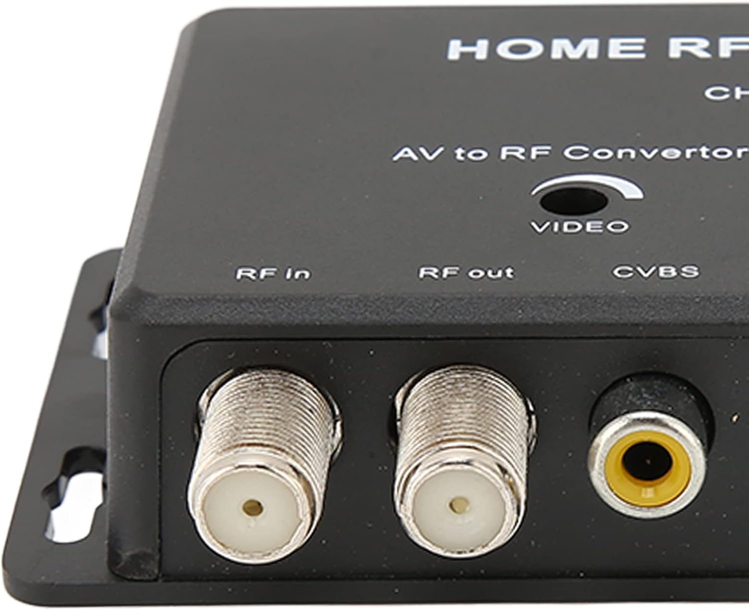
Figure 3.2: Input/Output Ports Detail. A closer look at the RF In, RF Out (F-type female connectors), and CVBS (RCA yellow) input ports. These are the primary connection points for your audio/video source and the television's RF input.

Figure 3.3: Control Functions Table. The underside of the modulator features a printed table detailing the functions of the 'CH+' and 'CH-' buttons. It explains how to select channels, set the sound carrier frequency (4.5/5.5/6.0/6.5MHz), and choose between PAL/NTSC TV formats by pressing the buttons for specific durations.
4. Setup Instructions
Follow these steps to properly set up your VBESTLIFE AV to RF Modulator:
- Connect AV Source: Connect your audio/video source (e.g., DVD player, set-top box, game console) to the modulator's AV input ports.
- Connect the yellow RCA cable from your AV source to the CVBS (yellow) input on the modulator.
- Connect the white RCA cable from your AV source to the L (white) audio input on the modulator.
- Connect the red RCA cable from your AV source to the R (red) audio input on the modulator.
- Connect to TV: Connect the modulator's RF output to your television's RF input (antenna/cable input).
- Use an RF coaxial cable (not included) to connect the RF Out port on the modulator to the antenna/cable input on your TV.
- Power On: Connect the supplied USB power cable to the USB 5V input on the modulator and plug the other end into a compatible USB power adapter (not included) or a USB port on your TV/device. The modulator will power on, and the channel display will illuminate.
- Tune TV: Turn on your television and tune it to the appropriate channel (e.g., Channel 21, which is the default setting for the modulator) to receive the signal from the modulator. You may need to perform a channel scan on your TV if the signal is not immediately found.
5. Operating Instructions
The VBESTLIFE TV Link Modulator comes with a default setting of Channel 21. You can adjust various settings using the CH+ and CH- buttons.
- Setting the Output Channel:
To change the RF output channel:
- Press the CH+ button to increase the channel number.
- Press the CH- button to decrease the channel number.
- The selected channel will be displayed on the digital screen.
- Setting the Sound Carrier Frequency:
To select the sound carrier frequency (4.5, 5.5, 6.0, or 6.5MHz):
- Press and hold the CH+ button for approximately 3 seconds. The display will cycle through the available frequencies. Release the button when your desired frequency is shown.
- Setting the TV Format (PAL/NTSC):
To select between PAL and NTSC TV formats:
- Press and hold the CH- button for approximately 3 seconds. The display will toggle between "PAL" and "NTSC". Release the button when your desired format is shown.
Note: Ensure the selected TV format (PAL or NTSC) matches the standard of your television and the AV source for optimal compatibility.
6. Specifications
Detailed technical specifications for the VBESTLIFE TV Link Modulator:
| Feature | Specification |
|---|---|
| Item Type | TV Link Modulator |
| Material | Plastic |
| TV Standard Format | PAL, NTSC |
| Channel Range (PAL) | 471.25~865MHz (21~69ch) |
| Channel Range (NTSC) | 471.25~885MHz (14~83ch) |
| Output Level | 85±5dBuV |
| Accompaniment System | M=4.5MHz, B,G=5.5MHz, I=6.0MHz, D,K=6.5MHz |
| A,V Connection | Female RCA |
| RF Input | F female |
| RF Output | F female |
| RF Output Impedance | 75 Ω (Unbalanced) |
| Video Input Impedance | 75 Ω |
| Default Factory Setting | Channel 21 (471.25MHz), PAL |
| Power Supply | USB DC 5V |
| Power Consumption | <1W |
| Operating Temperature | 0°C ~ +40°C |
| Dimensions | 5.04 x 4.09 x 1.34 inches (approximate) |
| Weight | 4.2 ounces (approximate) |
7. Troubleshooting
If you encounter issues with your VBESTLIFE TV Link Modulator, please refer to the following common problems and solutions:
- No Signal on TV:
- Ensure all cables (AV, RF, USB power) are securely connected.
- Verify the modulator is powered on (digital display should be lit).
- Check that your TV is tuned to the correct channel (default is Channel 21). Try scanning for channels on your TV.
- Confirm the TV format (PAL/NTSC) on the modulator matches your TV's standard.
- Ensure your AV source is powered on and outputting a signal.
- Poor Picture/Sound Quality:
- Check for loose or damaged cables.
- Ensure the AV source is providing a clean signal.
- Adjust the output channel on the modulator to avoid interference with other local RF signals.
- Verify the sound carrier frequency setting is appropriate for your region/TV.
- Modulator Not Powering On:
- Ensure the USB power cable is connected correctly to both the modulator and a working USB power source (e.g., wall adapter, TV USB port).
- Try a different USB power cable or power adapter.
8. Maintenance
To ensure the longevity and optimal performance of your VBESTLIFE TV Link Modulator, follow these simple maintenance guidelines:
- Cleaning: Use a soft, dry cloth to clean the exterior of the device. Do not use liquid cleaners or abrasive materials.
- Storage: Store the modulator in a cool, dry place away from direct sunlight and extreme temperatures when not in use.
- Handling: Avoid dropping the device or subjecting it to strong impacts.
- Ventilation: Ensure the device has adequate ventilation and is not covered during operation to prevent overheating.
9. Warranty and Support
Specific warranty details for the VBESTLIFE TV Link Modulator are typically provided at the point of purchase or within separate documentation. Please refer to your purchase receipt or contact the retailer/manufacturer directly for warranty information.
For technical support or further assistance, please contact VBESTLIFE customer service through their official channels or the retailer from whom you purchased the product.