1. Introduction
This manual provides detailed instructions for the safe and efficient operation of the East Tester ET5410A+/ET5411A+ Dual Channel Electronic Load 400W. This programmable DC electronic load utilizes high-performance, high-speed, high-precision chips, offering 1mV, 1mA resolution. It is designed for a wide range of applications including testing chargers, switching power supplies, linear power supplies, various batteries, industrial production lines, scientific research institutions, and other experimental research and development fields.
2. Safety Information
Please read and understand all safety warnings and operating instructions before using this device. Failure to do so may result in injury or damage to the equipment.
- Power Source: Ensure the device is connected to a stable power source within the specified voltage range.
- Ventilation: Do not block the ventilation openings. Ensure adequate airflow around the unit to prevent overheating.
- Environment: Operate the device in a dry, clean environment, away from flammable materials, moisture, and extreme temperatures.
- Connections: Always ensure proper polarity when connecting the load to the device. Incorrect polarity can cause damage.
- Overload Protection: The device includes over-voltage, over-current, and over-power protection. Do not attempt to operate beyond the specified limits.
- Maintenance: Refer to the maintenance section for cleaning and care. Do not attempt to service the unit yourself.
3. Product Overview
The East Tester ET5410A+/ET5411A+ is a versatile electronic load designed for precision testing. It features a compact design with a retractable handle for portability.
3.1 Key Features
- Provides CC, CV, CR, CP, and multiple basic measurement modes including CC+CV, CR+CV.
- Offers professional battery testing and LED testing.
- Dynamic test mode for evaluating power supply dynamic output performance.
- Scan test mode to assess power output continuity within a specified range.
- List mode to simulate various load state changes.
- Short-circuit test function.
- Remote measurement mode for improved high-current measurement accuracy.
- Supports external trigger input.
- Integrated audible alarm.
- Data storage function after power failure.
- Remote operation via RS-232 and USB device interfaces.
- Multiple safety protections: over-voltage, over-current, over-power, secondary over-temperature, and output reverse polarity protection.
- Intelligent fan speed control for reduced noise.
3.2 Front Panel Layout
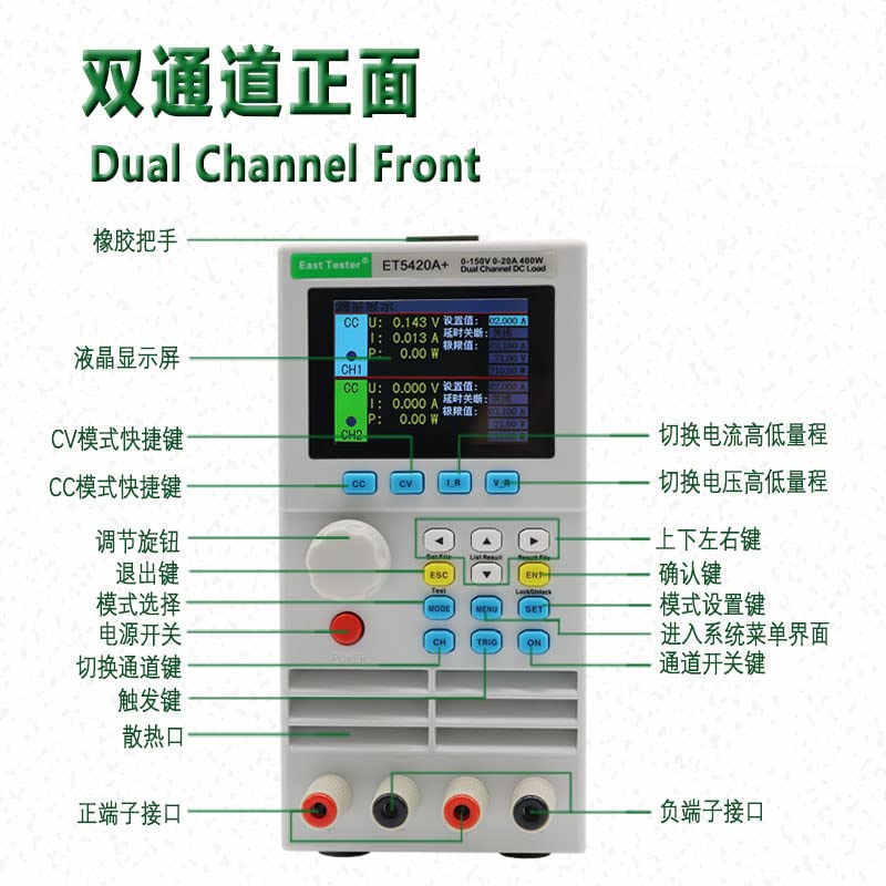
Image 1: Front Panel Layout of the ET5410A+ Electronic Load. This image shows the dual-channel front panel with labels indicating the LCD display screen, rubber handle, CV mode shortcut key, CC mode shortcut key, adjustment knob, exit key, mode selection, power switch, channel switch key, trigger key, heat dissipation vent, positive terminal interface, negative terminal interface, current high/low range switch, voltage high/low range switch, confirm key, mode setting key, system menu interface entry, and channel switch key. The display shows set values, alarm values, and measured values.
3.3 Physical Design

Image 2: Front view of the East Tester ET5410A+ electronic load, showcasing its compact design and clear display.

Image 3: The ET5410A+ electronic load being carried, highlighting its portable nature.
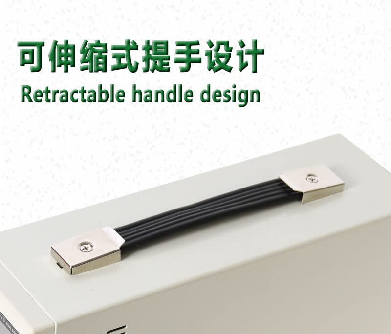
Image 4: Detail of the retractable handle design, providing convenience for transport.
3.4 Dimensions
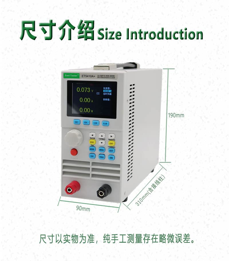
Image 5: Size Introduction. The diagram illustrates the approximate dimensions of the ET5410A+ electronic load: 190mm height, 90mm width, and 310mm depth (including wiring posts). Note that dimensions are based on the actual product, and slight errors may exist due to manual measurement.
4. Setup
- Unpacking: Carefully remove the electronic load from its packaging and inspect for any signs of damage.
- Placement: Place the unit on a stable, level surface with adequate ventilation space around it.
- Power Connection: Connect the provided power cord to the AC input on the rear panel of the device, then plug it into a suitable power outlet.
- Load Connection: Connect the device under test (DUT) to the positive (red) and negative (black) terminal interfaces on the front panel. Ensure correct polarity.
- Remote Control (Optional): If using remote control, connect the RS-232 or USB cable to the corresponding port on the device and your computer. Install any necessary drivers or software as per manufacturer instructions.
5. Operating Instructions
The ET5410A+/ET5411A+ offers various operating modes and functions. Familiarize yourself with the front panel controls as shown in Image 1.
5.1 Basic Operation
- Power On: Press the Power Switch to turn on the device. The LCD display will illuminate.
- Channel Selection: If using a dual-channel model, use the 'CH' (Channel Switch Key) to select the desired channel (CH1 or CH2).
- Mode Selection: Press the 'MODE' button to cycle through the basic operating modes: Constant Current (CC), Constant Voltage (CV), Constant Resistance (CR), and Constant Power (CP).
- Parameter Setting: Use the Adjustment Knob to change the value of the selected parameter. Press the knob to confirm or switch between digits. Use the arrow keys (Up/Down/Left/Right) for fine adjustments or cursor movement.
- Start/Stop: Press the 'ON' button to enable the load and begin testing. Press 'OFF' to disable the load.
- Exit/Back: Use the 'ESC' key to exit a menu or go back to the previous screen.
- Confirm: Use the 'ENT' key to confirm selections or enter sub-menus.
5.2 Advanced Modes
- CC+CV / CR+CV Modes: These combined modes allow for more complex load simulations. Select them via the 'MODE' button or dedicated shortcut keys if available.
- Battery Test: Access this mode through the menu ('MENU' button) to perform professional battery discharge tests. Set parameters like discharge current, cut-off voltage, and discharge time.
- LED Test: Similar to battery test, this mode is accessed via the menu for specific LED testing applications.
- Dynamic Test: Use this mode to simulate transient load changes and evaluate the dynamic response of power supplies. Configure step current/voltage, rise/fall times, and dwell times.
- Scan Test: This mode allows the load to sweep through a range of current or voltage values to test power supply continuity.
- List Mode: Program a sequence of load steps with different parameters (current, voltage, resistance, power, and duration) to simulate complex load profiles.
- Short-Circuit Test: Activate this function to simulate a short-circuit condition on the load. Exercise caution when using this mode.
- Remote Measurement: For high-current applications, connect sense wires to the remote sense terminals (if available) to compensate for voltage drop across the load wires, improving measurement accuracy.
- External Trigger: The device can be triggered externally for synchronized testing with other equipment. Refer to the detailed programming guide for trigger input specifications.
5.3 Safety Protections
The device incorporates multiple safety features:
- Over-Voltage Protection (OVP): Shuts down the load if the input voltage exceeds a set limit.
- Over-Current Protection (OCP): Disables the load if the input current exceeds a set limit.
- Over-Power Protection (OPP): Turns off the load if the input power exceeds a set limit.
- Over-Temperature Protection (OTP): Activates if the internal temperature becomes too high, protecting the device from thermal damage.
- Reverse Polarity Protection: Protects the device from damage if the input polarity is accidentally reversed.
These protection parameters can be configured via the system menu. Always set appropriate protection limits for your application.
6. Maintenance
- Cleaning: Disconnect the power before cleaning. Use a soft, dry cloth to wipe the exterior of the device. Do not use abrasive cleaners or solvents.
- Ventilation: Regularly check that the ventilation openings are clear of dust and debris.
- Storage: When not in use for extended periods, store the device in a cool, dry place, protected from dust and direct sunlight.
- Calibration: Periodic calibration by qualified personnel is recommended to maintain measurement accuracy.
7. Troubleshooting
If you encounter issues with your electronic load, refer to the following common troubleshooting steps:
- Device Not Powering On: Check the power cord connection and the power outlet. Ensure the power switch is in the 'ON' position.
- No Load Current/Voltage: Verify that the load is properly connected to the terminals with correct polarity. Ensure the 'ON' button has been pressed to enable the load. Check if any protection functions (OVP, OCP, OPP) have been triggered.
- Inaccurate Readings: Ensure remote sense wires are correctly connected if using remote measurement. Check for loose connections. Consider if calibration is required.
- Overheating: Ensure ventilation openings are not blocked. Reduce the load if operating near maximum capacity in a high ambient temperature.
- Error Messages: Refer to the full product manual (if available) for specific error code explanations and solutions.
If the problem persists, contact customer support or a qualified service technician.
8. Specifications
| Specification | Value |
|---|---|
| Brand | East Tester |
| Item Model Number | ET5410+ |
| Manufacturer | zhongchuang |
| Power Source | Battery Powered (Note: This likely refers to the internal control circuit, the main load power is external) |
| Measurement Type | Multimeter functions (Voltage, Current, Power) |
| UPC | 659252931800 |
| Package Dimensions | 40.1 x 29.1 x 19.1 cm |
| Item Weight | 3.59 kilograms |
| Date First Available | June 20, 2022 |
9. Warranty and Support
For warranty information, technical support, or service inquiries, please contact your retailer or the manufacturer directly. Keep your purchase receipt as proof of purchase.


