
1. Introduction
The GEYA GRT8-S1 is an asymmetric cycle time relay designed for various industrial and home automation applications. It offers two primary time functions: cycler beginning with a pulse (ON first) and cycler beginning with a pause (OFF first). This relay features a wide time scale from 0.1 seconds to 100 days, divided into 10 time ranges, and is equipped with an LED indicator for relay status. Its ultra-small size allows for convenient 35mm DIN rail mounting.
This manual provides detailed instructions for the safe installation, configuration, and operation of your GRT8-S1 relay.
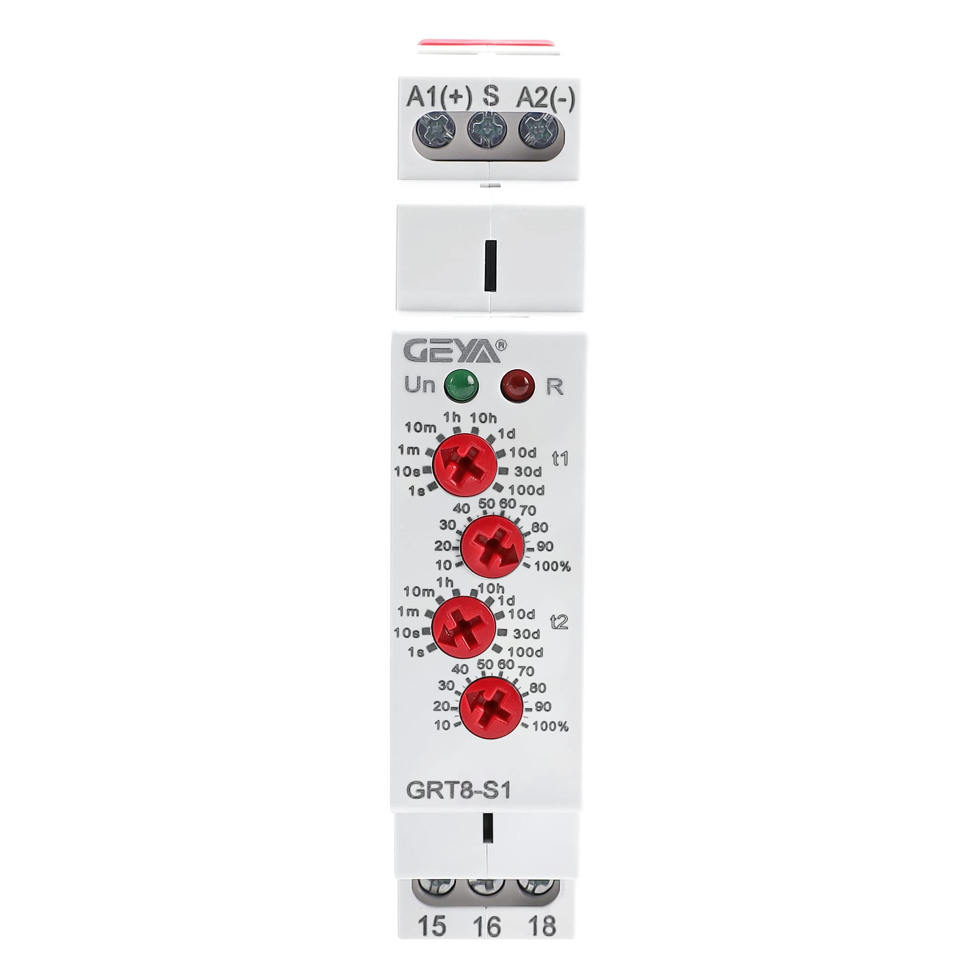
Figure 1: GEYA GRT8-S1 Asymmetric Cycle Time Relay
2. Safety Information
- Always disconnect power before installation, wiring, or maintenance to prevent electric shock.
- Installation should be performed by qualified personnel in accordance with local electrical codes and regulations.
- Ensure the relay's voltage and current ratings match your application requirements.
- Do not expose the device to moisture, extreme temperatures, or corrosive environments.
- Verify all connections are secure before applying power.
3. Product Overview
The GRT8-S1 features clearly labeled terminals and adjustment potentiometers for easy configuration. The front panel includes LED indicators for power supply and output status.

Figure 2: GRT8-S1 Component Layout and Indicators
Key Components:
- Supply Terminals (A1, A2): For connecting the power supply.
- Function Selection (S-A1 Jumper): Determines the starting state of the cycle.
- LED Indication: Green LED for power supply (Un), Red LED for output (R).
- T1 ON Time Adjustable Potentiometer: Sets the duration of the ON state.
- T2 OFF Time Adjustable Potentiometer: Sets the duration of the OFF state.
- Output Terminals (15, 16, 18): Single Pole Double Throw (SPDT) contacts for controlling the load.
4. Setup
4.1 Mounting
The GRT8-S1 is designed for 35mm DIN rail mounting. Simply clip the relay onto the DIN rail in your electrical enclosure. Ensure it is securely fastened.
4.2 Wiring Diagram
Connect the power supply and load according to the wiring diagrams below. The GRT8-S1 is a 1SPDT (Single Pole Double Throw) relay, meaning it has one common terminal (15), one normally closed (NC) terminal (16), and one normally open (NO) terminal (18).
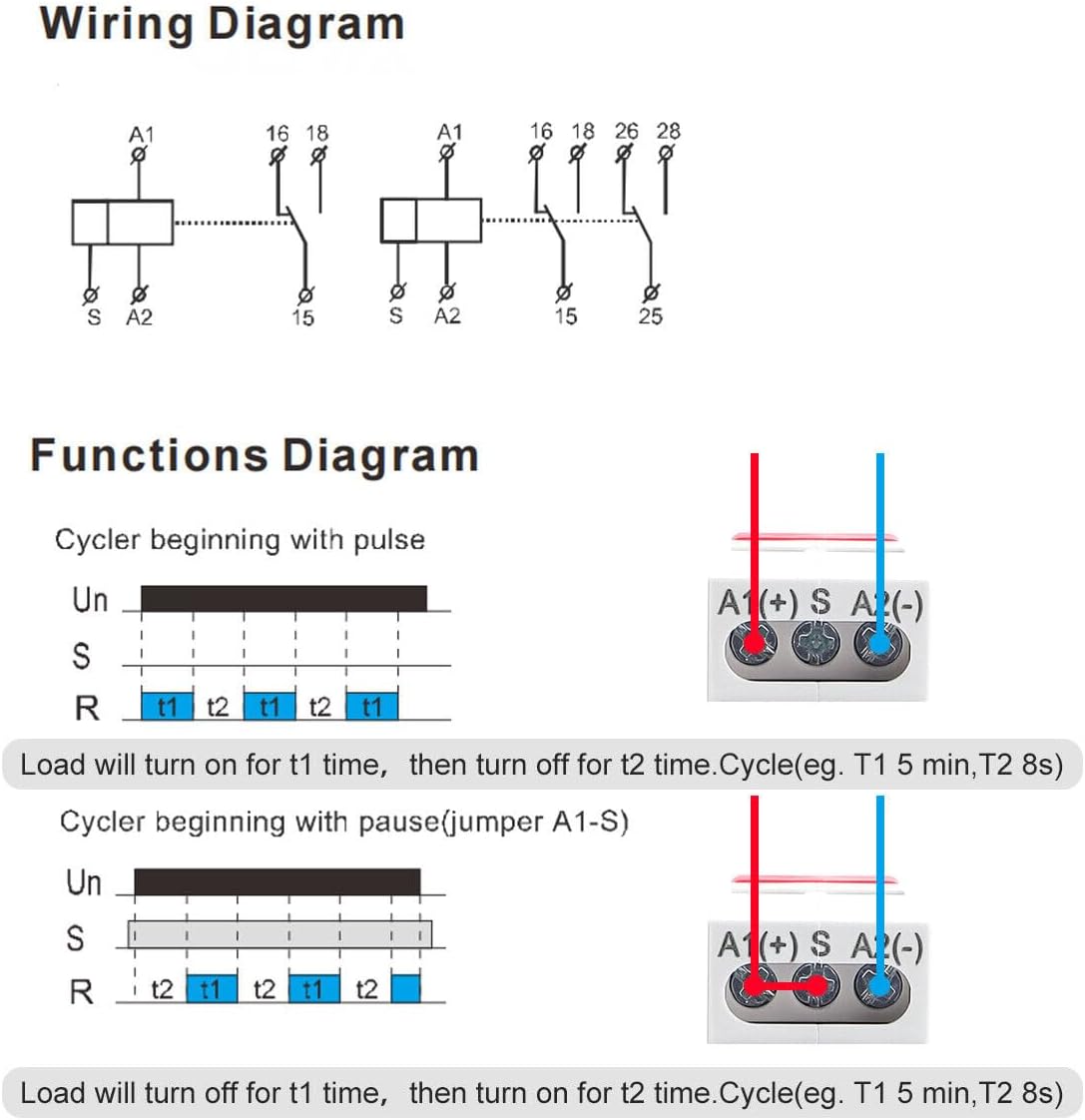
Figure 3: GRT8-S1 Wiring Diagram
Example Wiring for a Load:

Figure 4: Example Wiring with a Bulb
In this example, the bulb works for a period (T1), stops for a period (T2), and continues to cycle until the relay is powered off.
4.3 Function Selection
The GRT8-S1 offers two operating modes, selected by an external jumper between terminals S and A1:
- Cycler beginning with pulse (ON first): No jumper between S and A1. The load turns ON for T1, then OFF for T2.
- Cycler beginning with pause (OFF first): Jumper connected between S and A1. The load turns OFF for T1, then ON for T2.

Figure 5: Function Selection and Timing Diagrams
4.4 Time Setting
The relay has two potentiometers for setting the ON time (T1) and OFF time (T2), each with a time range selector and a percentage knob. The time scale ranges from 0.1 seconds to 100 days.
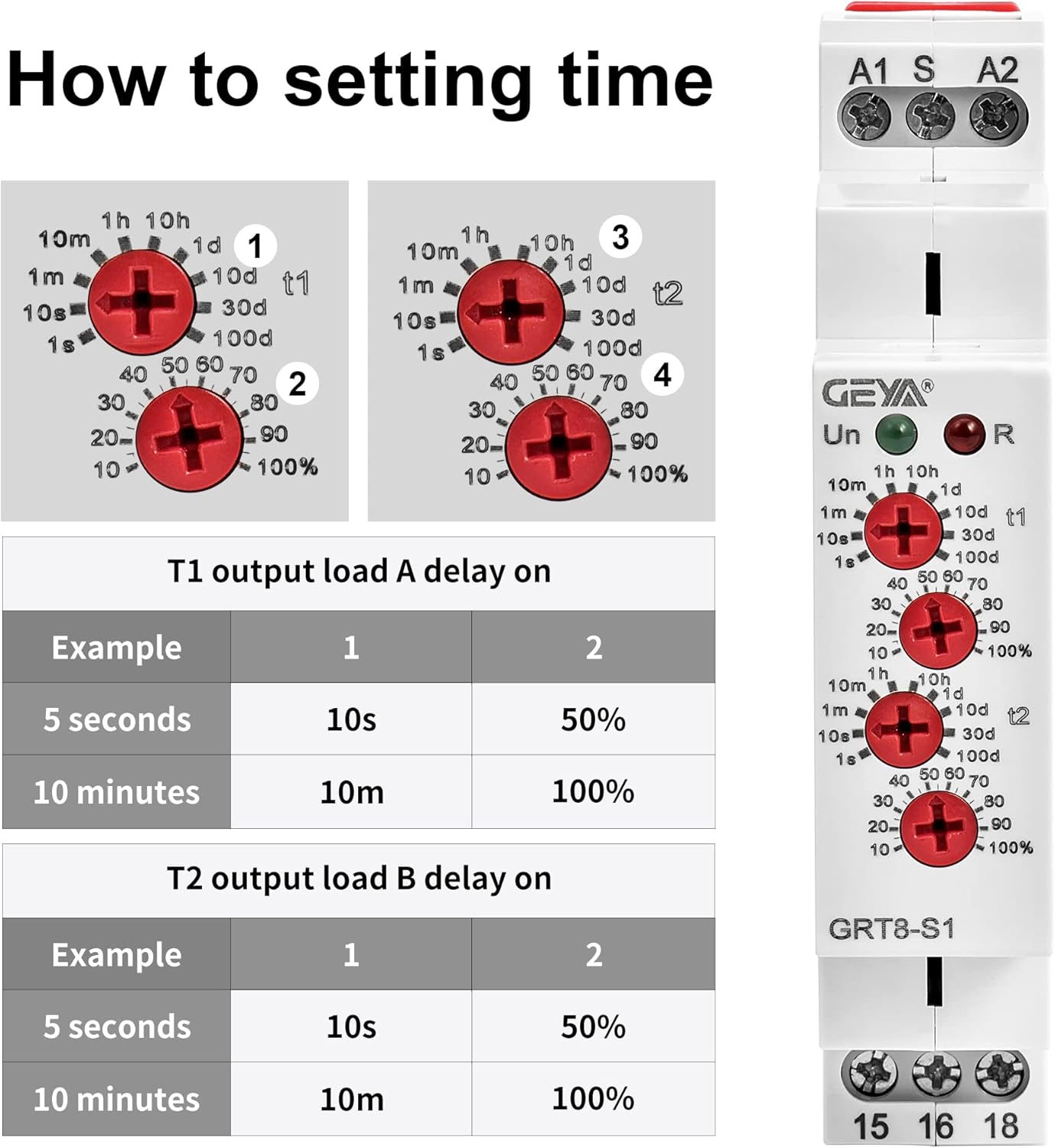
Figure 6: How to Set Time (T1 and T2)
To set a specific time:
- Select Time Range: Use the upper knob (1 or 3) to select the desired time range (e.g., 1s-10s, 1min-10min, 1h-10h, 1d-10d).
- Adjust Percentage: Use the lower knob (2 or 4) to set the percentage within the selected time range. For example, if the range is 10 minutes and the percentage is 50%, the time will be 5 minutes.

Figure 7: Time Setting Example Calculation
5. Operation
Once wired and configured, apply power to terminals A1 and A2. The green LED (Un) will illuminate, indicating the power supply is active. The red LED (R) indicates the status of the output relay.
- Cycler beginning with pulse (No S-A1 jumper): The red LED will turn ON for the set T1 duration, then turn OFF for the set T2 duration. This cycle repeats as long as power is supplied.
- Cycler beginning with pause (S-A1 jumper): The red LED will remain OFF for the set T1 duration, then turn ON for the set T2 duration. This cycle repeats as long as power is supplied.

Video 1: GEYA GRT8-S1 Product Overview and Operation Demonstration
6. Maintenance
The GEYA GRT8-S1 is designed for reliable, long-term operation with minimal maintenance. Periodically inspect the relay and its connections for any signs of damage, loose wiring, or overheating. Ensure the environment remains within the specified operating temperature and humidity ranges. No user-serviceable parts are inside the unit.
7. Troubleshooting
- Relay not activating: Check the power supply to terminals A1 and A2. Ensure the green 'Un' LED is illuminated. Verify wiring connections to the load.
- Incorrect timing: Recheck the settings on the T1 and T2 potentiometers, including both the time range and percentage knobs. Ensure the selected function (pulse first or pause first) is correct for your application.
- Relay failure or erratic behavior: If the relay fails prematurely or behaves erratically, ensure the connected load's current and voltage do not exceed the relay's rated capacity, especially for inductive loads. Inductive loads (e.g., motors, solenoids) can cause high inrush currents or voltage spikes that may damage the relay if not properly managed or if the relay's specifications are exceeded. Consider using an external contactor for high inductive loads.
- No output indication: If the red 'R' LED does not illuminate when expected, check the load circuit for open connections or faults.
8. Specifications
The following table details the technical specifications for the GEYA GRT8-S1 Asymmetric Cycle Time Relay:

Figure 8: Technical Parameters
| Parameter | Value (GRT8-S1) |
|---|---|
| Function | Asymmetric cycler time relay |
| Supply Terminals | A1-A2 |
| Voltage Range | AC/DC 12-240V (50-60Hz) |
| Burden | AC 0.09-3VA/DC 0.05-1.7W |
| Power Input | max. 6VA/1.3W |
| Supply Indication | Green LED |
| Time Ranges | 0.1s-100 days (10 ranges) |
| Time Setting | Potentiometer |
| Time Deviation | 10% mechanical setting |
| Repeat Accuracy | 0.2% set value stability |
| Temperature Coefficient | 0.05%/°C, at 20°C (68°F) |
| Output | 1 × SPDT |
| Current Rating | 1 × 16A (AC1) |
| Switching Voltage | 250VAC/24VDC |
| Min. Breaking Capacity DC | 500mW |
| Output Indication | Red LED |
| Mechanical Life | 1 × 10⁷ |
| Electrical Life (AC1) | 1 × 10⁵ |
| Reset Time | max. 200ms |
| Operating Temperature | -20°C to +55°C (-4°F to 131°F) |
| Storage Temperature | -35°C to +75°C (-22°F to 158°F) |
| Mounting/DIN Rail | DIN rail EN/IEC 60715 |
| Protection Degree | IP40 for front panel/IP20 terminals |
| Operating Position | Any |
| Overvoltage Category | III. |
| Pollution Degree | 2 |
| Max. Cable Size (mm²) | Solid wire max. 1x2.5 or 2x1.5 / with sleeve max. 1x2.5 (AWG 12) |
9. Warranty and Support
GEYA products are manufactured to high-quality standards and are typically covered by a manufacturer's warranty against defects in materials and workmanship. For specific warranty terms and conditions, please refer to the documentation provided with your purchase or contact GEYA customer support.
For technical assistance, troubleshooting, or product inquiries, please visit the official GEYA store or contact their customer service department. You can find more information and contact details on the GEYA Brand Store.

