Introduction
The SELF ELECTRONICS HZK218B is an electronic relay equipped with an infrared (IR) sensor, specifically designed for automated lighting control in cabinets and similar enclosures. This device intelligently switches connected equipment on or off based on the opening or closing of a door, providing convenience and energy efficiency. It supports various loads up to 250W and can be integrated into both mains voltage and low voltage LED systems.

Main view of the HZK218B Electronic IR Sensor Switch with its integrated infrared sensor.
Safety Information
Please read all safety instructions carefully before installation and operation. Failure to follow these instructions may result in electric shock, fire, or serious injury.
- Always disconnect power at the circuit breaker before installing or servicing the device.
- Installation should be performed by a qualified electrician in accordance with all local and national electrical codes.
- Do not exceed the maximum load capacity of 250W.
- Ensure proper insulation and wiring connections to prevent short circuits.
- Keep the device away from water and excessive moisture.
- Do not attempt to disassemble or modify the device.
Package Contents
Verify that all components are present before beginning installation:
- 1 x HZK218B Electronic IR Sensor Switch with integrated sensor and cable
- Mounting screws (as shown in image)

The HZK218B relay and sensor, along with the included mounting screws for installation.
Setup and Installation
Follow these steps for proper installation of your HZK218B sensor switch.
1. Wiring Connections
The HZK218B can be wired for either mains voltage loads or low voltage LED systems. Refer to the diagram below for correct connections.

Wiring diagrams for the HZK218B, illustrating connections for both mains voltage (top) and low voltage (bottom) applications.
- Mains Voltage Connection (AC 100-240V): Connect the input wires to your AC power source and the output wires to your lighting fixture (e.g., incandescent, halogen, or LED lamps designed for mains voltage). Ensure the total load does not exceed 250W.
- Low Voltage LED Connection: Connect the input wires to your AC power source. The output of the HZK218B should then connect to the primary side of a constant voltage LED driver/charger. The LED strip or fixture connects to the secondary side of the LED driver.
- Use the screw terminals for secure connections.
2. Sensor Placement and Detection
The IR sensor detects objects within its range. For optimal performance in cabinets, position the sensor where it can detect the door opening and closing effectively.

Diagram illustrating the sensor's ON/OFF operation based on cabinet door position, with a maximum detection range of 10 cm.
- The sensor has a maximum detection range of 10 cm.
- For reliable operation, a detection range of less than 5 cm is recommended. This ensures the sensor accurately responds to the door's movement without false triggers.
- Mount the sensor flush with the cabinet surface or in a small drilled hole, ensuring its lens is unobstructed.

Detailed view of the HZK218B relay and sensor, emphasizing the recommended detection range of less than 5 cm for optimal performance.
3. Mounting the Relay
The relay unit can be mounted using the provided screws. Choose a secure location inside the cabinet or near the lighting fixture, ensuring it is protected from physical damage and moisture.
- Use the mounting screws to fix the relay securely.
- Ensure adequate ventilation around the relay if installed in an enclosed space.
Operating Instructions
The HZK218B operates automatically based on the detection of the cabinet door.
- When the cabinet door is closed, the IR sensor detects the door, and the connected light will be OFF.
- When the cabinet door is opened, the IR sensor no longer detects the door (as it moves out of range), and the connected light will automatically turn ON.
- The light will remain ON as long as the door is open and the sensor is unobstructed.
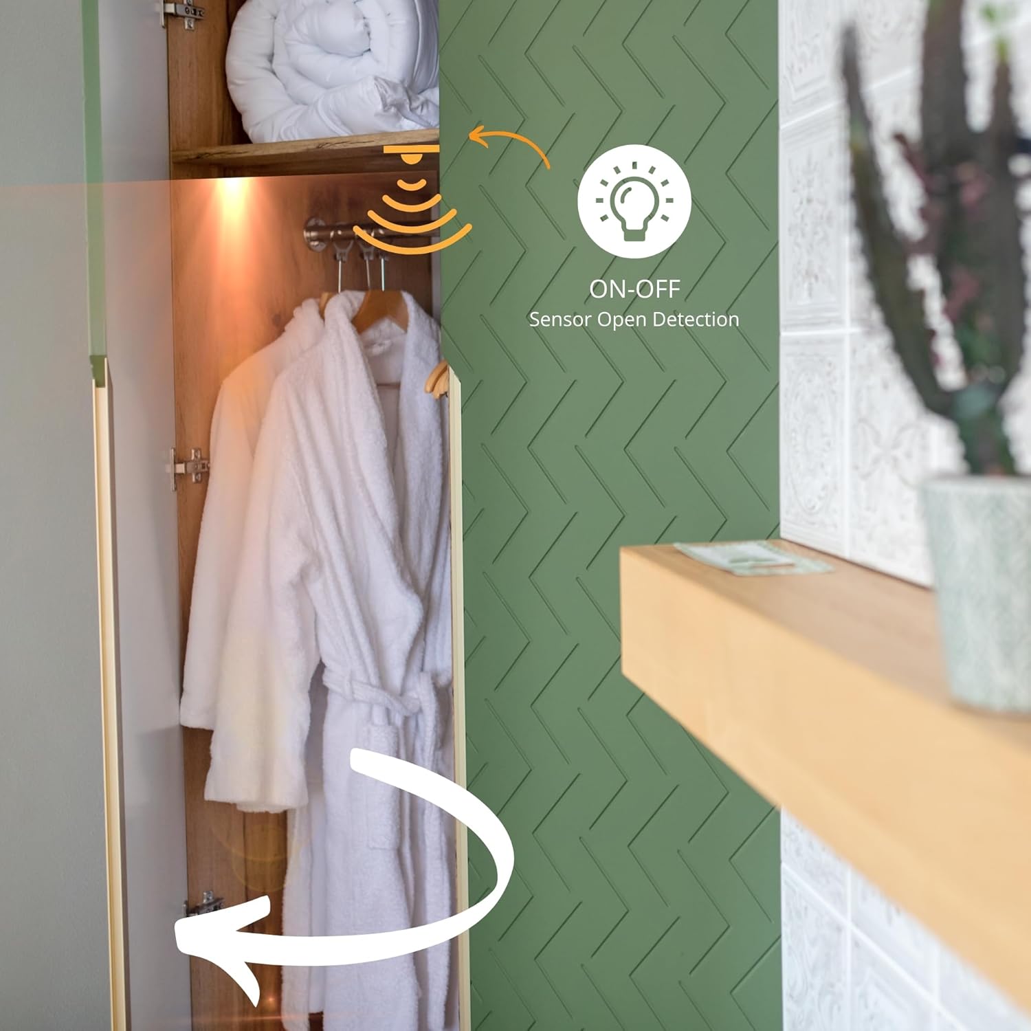
Illustration of the sensor's function in a cabinet, demonstrating automatic light activation upon door opening.
Maintenance
The HZK218B Electronic IR Sensor Switch requires minimal maintenance.
- Cleaning: Periodically wipe the sensor lens with a soft, dry cloth to ensure it remains free of dust and debris, which could affect its detection capabilities. Do not use abrasive cleaners or solvents.
- Inspection: Occasionally check the wiring connections to ensure they remain secure.
- No user-serviceable parts inside. Do not open the relay housing.
Troubleshooting
If you encounter issues with your HZK218B, refer to the following common problems and solutions:
| Problem | Possible Cause | Solution |
|---|---|---|
| Light does not turn ON when door opens. |
|
|
| Light does not turn OFF when door closes. |
|
|
| Intermittent operation. |
|
|
Specifications
Technical specifications for the HZK218B Electronic IR Sensor Switch:
| Feature | Detail |
|---|---|
| Model Number | HZK218C |
| Brand | SELF ELECTRONICS |
| Input Voltage | 100-240VAC, 50/60Hz |
| Max. Lighting Load | 250W |
| Rated Current | 1A |
| Detection Type | Infrared (IR) Sensor |
| Max. Detection Range | 10 cm (Recommended: < 5 cm) |
| Operating Mode | Automatic |
| Connector Type | Screw Terminals |
| Contact Material | Copper |
| Contact Type | Normally Open |
| Mounting Type | Screw Mount |
| Product Dimensions (L x W x H) | 8.3 x 3.5 x 1.9 cm (3-1/4" x 1-3/8" x 3/4") |
| Weight | 70 grams |
| Certifications | Certified (CE, KEMA EUR, EMC) |

Technical drawing displaying the dimensions of the HZK218B Electronic IR Sensor Switch in both millimeters and inches.
Warranty and Support
While specific warranty details are not provided in the product information, SELF ELECTRONICS products are generally known for their reliability and certification.
For technical support, warranty claims, or further assistance, please contact your retailer or the manufacturer directly. Keep your purchase receipt as proof of purchase.
Manufacturer: SELF ELECTRONICS CO LTD