1. Introduction
Thank you for choosing the MESTEK Digital Clamp Meter Multimeter CM83E. This device is a professional, auto-ranging digital clamp meter designed for accurate measurement of AC/DC current, AC/DC voltage, resistance, capacitance, frequency, temperature, diodes, and continuity. It features True-RMS measurement, Non-Contact Voltage (NCV) detection, a backlit LCD display, and an LED flashlight, making it suitable for various electrical testing applications in residential, commercial, and automotive settings. Please read this manual thoroughly before use to ensure safe and proper operation.

Figure 1: MESTEK Digital Clamp Meter CM83E with included accessories. This image shows the main unit, red and black test leads, a temperature probe, and a black zippered carrying case.
2. Safety Information
To prevent possible electrical shock, fire, or personal injury, please read all safety information before you use the product.
- Always adhere to local and national safety codes.
- Do not use the meter if it appears damaged or if the test leads are damaged.
- Verify the meter's operation by measuring a known voltage or current before use.
- Do not apply more than the rated voltage, as marked on the meter, between the terminals or between any terminal and earth ground.
- Use caution when working with voltages above 30V AC RMS, 42V peak, or 60V DC. These voltages pose a shock hazard.
- Keep fingers behind the finger guards on the test probes during measurements.
- Disconnect the circuit power and discharge all high-voltage capacitors before testing resistance, continuity, diodes, or capacitance.
- Remove the test leads from the meter before opening the battery cover.
- Replace the batteries as soon as the low battery indicator appears to avoid incorrect readings.
- The meter is rated CAT III 1000V and CAT IV 600V. Do not exceed these ratings.
3. Product Overview
The MESTEK CM83E is a versatile tool for electrical measurements. Familiarize yourself with its components:

Figure 2: Labeled diagram of the MESTEK CM83E clamp meter, indicating the NCV sensor, clamp head, flashlight, clamp head trigger, SEL/Backlight function key, ZERO switch key, NCV button, function selection dial, dual screen display, and test lead inputs.
3.1 Key Features
- True-RMS Measurement: Provides accurate readings for non-sinusoidal waveforms.
- Auto-Ranging: Automatically selects the correct measurement range.
- 6000 Counts Display: High-resolution digital display.
- Non-Contact Voltage (NCV): Detects AC voltage without physical contact.
- Backlit LCD & Flashlight: Improves visibility in low-light conditions.
- Data Hold: Freezes the displayed reading.
- Auto Power Off: Conserves battery life after 10 minutes of inactivity.
- ZERO Function: Used for DC current measurement to eliminate residual magnetism.
- VFD & LoZ Modes: For specialized voltage measurements.
4. Setup
4.1 Unpacking and Contents Check
Carefully unpack the clamp meter and verify that all items are present:
- MESTEK Digital Clamp Meter (CM83E)
- Test Leads (Red and Black)
- K-Type Thermocouple (Temperature Probe)
- Screwdriver (for battery compartment)
- 2 x 1.5V AAA Batteries
- Carrying Case
- User Manual (this document)

Figure 3: The MESTEK CM83E clamp meter shown with its complete set of accessories, including test leads, temperature probe, screwdriver, batteries, and carrying case.
4.2 Battery Installation
- Ensure the meter is turned OFF.
- Locate the battery compartment cover on the back of the meter.
- Use the provided screwdriver to loosen the screw on the battery cover.
- Remove the battery cover.
- Insert two (2) 1.5V AAA batteries, observing the correct polarity (+ and -) as indicated inside the compartment.
- Replace the battery cover and tighten the screw.
5. Operating Instructions
This section details how to use the various measurement functions of your MESTEK CM83E clamp meter.
5.1 Function Selection
Rotate the central dial to select the desired measurement function. The meter will automatically select the appropriate range for most measurements.
5.2 AC/DC Voltage Measurement (V)
- Insert the red test lead into the "INPUT" terminal and the black test lead into the "COM" terminal.
- Turn the function dial to the V~ (AC Voltage) or V- (DC Voltage) position.
- Connect the test probes in parallel to the circuit or component you wish to measure.
- Read the voltage value on the display.
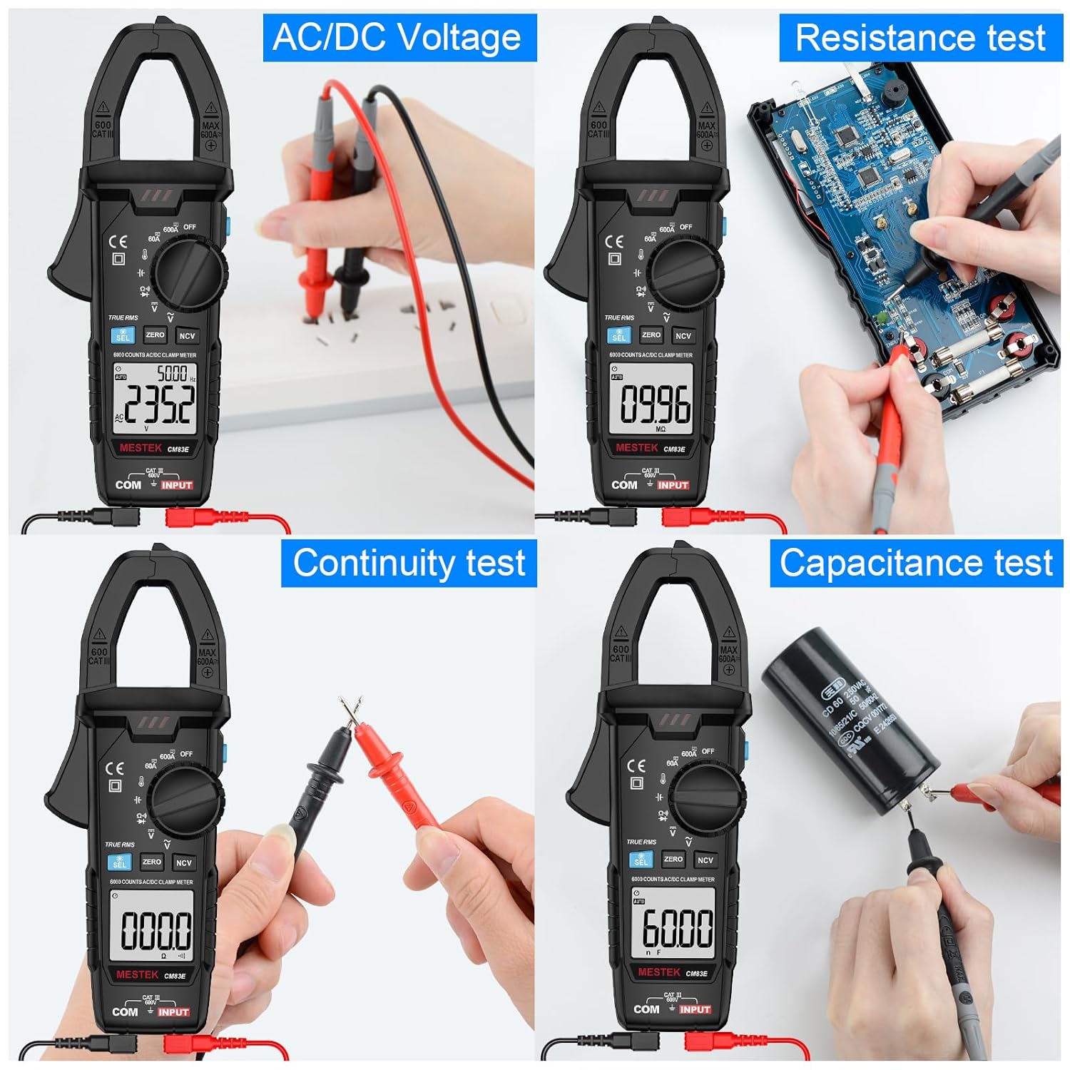
Figure 4: Demonstrates the meter performing various tests including AC/DC Voltage, Resistance, Continuity, and Capacitance. The top-left panel shows voltage measurement with test leads connected to a power source.
5.3 AC/DC Current Measurement (A) - Clamp Function
The clamp function allows measurement of current without breaking the circuit.
- Turn the function dial to the 60A or 600A position for AC or DC current.
- For DC current measurement, press the ZERO button before clamping to eliminate residual magnetism and ensure accuracy.
- Press the clamp trigger to open the clamp jaws.
- Enclose only one conductor (wire) within the clamp jaws. Do not clamp around multiple wires or a power cord with both live and neutral wires, as this will result in a zero reading.
- Release the trigger to close the jaws securely around the conductor.
- Read the current value on the display.

Figure 5: Illustrates the correct method for measuring current with a clamp meter (right panel, clamping a single wire) versus an incorrect method (left panel, clamping a power cord with multiple wires, which will show zero current).

Figure 6: The clamp meter is shown measuring DC current on a car battery cable, demonstrating its application for automotive electrical diagnostics.
5.4 Resistance Measurement (Ω)
- Insert the red test lead into the "INPUT" terminal and the black test lead into the "COM" terminal.
- Turn the function dial to the Ω position.
- Ensure the circuit or component is de-energized before connecting the test probes across the component.
- Read the resistance value on the display.
5.5 Capacitance Measurement (╪)
- Insert the red test lead into the "INPUT" terminal and the black test lead into the "COM" terminal.
- Turn the function dial to the ╪ position.
- Ensure the capacitor is fully discharged before connecting the test probes.
- Connect the test probes across the capacitor terminals.
- Read the capacitance value on the display.
5.6 Continuity Test (#)
- Insert the red test lead into the "INPUT" terminal and the black test lead into the "COM" terminal.
- Turn the function dial to the # (Continuity) position.
- Connect the test probes across the circuit or component.
- If the resistance is below approximately 50Ω, the buzzer will sound, indicating continuity.
5.7 Diode Test (►|)
- Insert the red test lead into the "INPUT" terminal and the black test lead into the "COM" terminal.
- Turn the function dial to the ►| (Diode) position.
- Connect the red probe to the anode and the black probe to the cathode of the diode.
- The display will show the forward voltage drop. Reverse the probes; an open circuit (OL) reading indicates a good diode.
5.8 Temperature Measurement (°C/°F)
- Turn the function dial to the °C/°F position.
- Insert the K-type thermocouple into the "INPUT" and "COM" terminals, observing polarity.
- Place the thermocouple tip on or near the object whose temperature you wish to measure.
- Read the temperature on the display. Press the SEL button to switch between Celsius and Fahrenheit.

Figure 7: The clamp meter is shown measuring temperatures using the K-type thermocouple in various scenarios: on ice, within an air conditioning vent, and in a cup of hot tea.
5.9 Non-Contact Voltage (NCV) Detection
- Turn the function dial to any position, then press the NCV button.
- Move the NCV sensor (located at the top of the clamp head) close to the conductor or outlet.
- The meter will emit an audible beep and the NCV indicator light will flash, with increasing frequency as it gets closer to a live voltage source.

Figure 8: The clamp meter is used to detect AC voltage without physical contact, with its NCV sensor positioned near an electrical outlet.
5.10 Additional Functions
- SEL Button: Used to switch between different measurement modes within a single dial position (e.g., AC/DC voltage, Celsius/Fahrenheit).
- ZERO Button: Primarily used for DC current measurement to zero out any offset before taking a reading.
- HOLD Button: Press to freeze the current reading on the display. Press again to release.
- Backlight & Flashlight: Press and hold the SEL button to activate the backlight. The flashlight button (often integrated with HOLD or a separate button) illuminates the work area.
- Auto Power Off: The meter will automatically power off after approximately 10 minutes of inactivity to save battery.

Figure 9: The clamp meter's large LCD screen is shown with its backlight activated, and the integrated flashlight illuminates the surrounding electrical panel, enhancing visibility in dark environments.
6. Maintenance
6.1 Cleaning
Wipe the case with a damp cloth and mild detergent. Do not use abrasives or solvents. Keep the terminals free of dirt and moisture.
6.2 Battery Replacement
When the low battery indicator appears on the display, replace the batteries promptly to ensure accurate readings. Refer to section 4.2 for battery installation instructions.
6.3 Storage
If the meter is not used for an extended period, remove the batteries to prevent leakage and store the meter in its carrying case in a dry, cool environment.
7. Troubleshooting
| Problem | Possible Cause | Solution |
|---|---|---|
| Meter does not power on. | Dead or incorrectly installed batteries. | Check battery polarity or replace batteries. |
| "OL" (Overload) displayed. | Measurement exceeds the selected range or meter's maximum capacity. | Select a higher range (if available) or ensure the measured value is within the meter's specifications. |
| Inaccurate DC current reading. | Residual magnetism in the clamp jaws. | Press the ZERO button before clamping the conductor. |
| No continuity beep. | Resistance is too high or circuit is open. | Verify the circuit is complete and resistance is below 50Ω. |
| NCV not detecting voltage. | Sensor not close enough, or voltage is too low. | Ensure the NCV sensor is directly over the live wire. Test on a known live circuit. |
8. Specifications
| Parameter | Range / Value |
|---|---|
| Display | 6000 Counts |
| AC Current | 60A / 600A |
| DC Current | 60A / 600A |
| AC Voltage | 600V |
| DC Voltage | 600V |
| Resistance | Up to 60MΩ |
| Capacitance | Up to 60mF |
| Temperature | -20°C to 1000°C (-4°F to 1832°F) |
| Diode Test | Yes |
| Continuity Test | Yes (Buzzer at < 50Ω) |
| NCV Detection | Yes |
| True-RMS | Yes |
| Auto-Ranging | Yes |
| Auto Power Off | Approx. 10 minutes |
| Power Supply | 2 x 1.5V AAA Batteries |
| Safety Rating | CAT III 1000V, CAT IV 600V |
| Dimensions | 7.87 x 2.95 x 1.46 inches |
| Weight | 6.88 ounces (195 grams) |
9. Warranty and Customer Support
MESTEK provides a 24-month after-sale service and technical support for this product. If the clamp meter is damaged within 24 months of purchase, please contact MESTEK customer service for assistance or replacement.
For technical inquiries or support, please refer to the contact information provided with your purchase or visit the official MESTEK website.