Introduction
The Yeceny WA-2608 Digital Amplified Outdoor HD TV Antenna is designed to receive digital UHF/VHF television signals, providing high-quality HDTV picture for local free-to-air channels. This antenna features a built-in 360-degree rotating motor controlled by a wireless remote, allowing for optimal signal reception. It supports connection to two televisions simultaneously without requiring an additional splitter.
Package Contents
Please verify that all items listed below are included in your package:
- WA-2608 Digital Amplified Outdoor HD TV Antenna Unit
- Mounting Pole (J-shaped)
- Wireless Remote Control
- Power Supply Adapter
- 60 Ft RG6 Coaxial Cable
- Coaxial Grounding Block
- Instruction Manual

Figure 1: Complete package contents of the WA-2608 antenna system.
Setup & Installation
1. Antenna Assembly
The antenna features a snap-on design for tool-free assembly. Carefully unfold the antenna elements and secure them into their designated slots until they click into place. Ensure all connections are firm.

Figure 2: Tool-free assembly of antenna elements.
2. Mounting the Antenna
Select an optimal outdoor location for mounting, such as a roof, attic, chimney, eave, or mast. The included J-shaped mounting pole can be affixed to a sturdy surface using appropriate hardware (not included, but typically screws or bolts). Ensure the mounting location allows for clear line-of-sight to broadcast towers and permits the antenna's 360-degree rotation without obstruction.

Figure 3: Example of antenna mounted on a pole.
3. Wiring and Connection
- Connect one end of the 60 ft RG6 coaxial cable to the ANT port on the antenna unit.
- Route the coaxial cable from the antenna to the indoor power supply/control box.
- Connect the other end of the coaxial cable to the 'ANT' input on the power supply/control box.
- Connect the power supply adapter to the control box and plug it into a standard electrical outlet.
- Connect your television(s) to the 'TV1' and/or 'TV2' output ports on the control box using additional coaxial cables (not included).
- For optimal safety, utilize the included coaxial grounding block. Connect the antenna's coaxial cable to one side of the grounding block and then connect the other side to the 'ANT' input on the control box. Ensure the grounding block is properly grounded to a suitable ground rod or building ground system.

Figure 4: The included 60-foot triple-shielded RG6 coaxial cable.

Figure 5: Coaxial grounding block for lightning protection.
Operating Instructions
Once the antenna is fully assembled, mounted, and connected, power on the control box using the ON/OFF switch. The control box features an infrared receiver for the wireless remote control.
Remote Control Functions:
- Rotation Button: Press the rotation button on the remote control to initiate the antenna's 360-degree rotation. This allows you to scan for and optimize signal reception from various directions.
- Indicator Lights: The control box features indicator lights:
- RED LIGHT: Indicates power is on.
- GREEN LIGHT: Indicates the antenna is currently rotating.
- YELLOW LIGHT: Indicates a potential issue with the power supply or cable connection. Check all connections if this light appears.
After rotating the antenna, perform a channel scan on your television to find available local channels. Adjust the antenna direction as needed to achieve the best signal quality for your desired channels.

Figure 6: Antenna control box and remote control.

Figure 7: The antenna's 360-degree rotation capability.
Dual TV Output
The WA-2608 antenna system is designed to support two televisions simultaneously without the need for an external splitter. Simply connect a second television to the 'TV2' output port on the control box. Both televisions can then receive available channels independently.
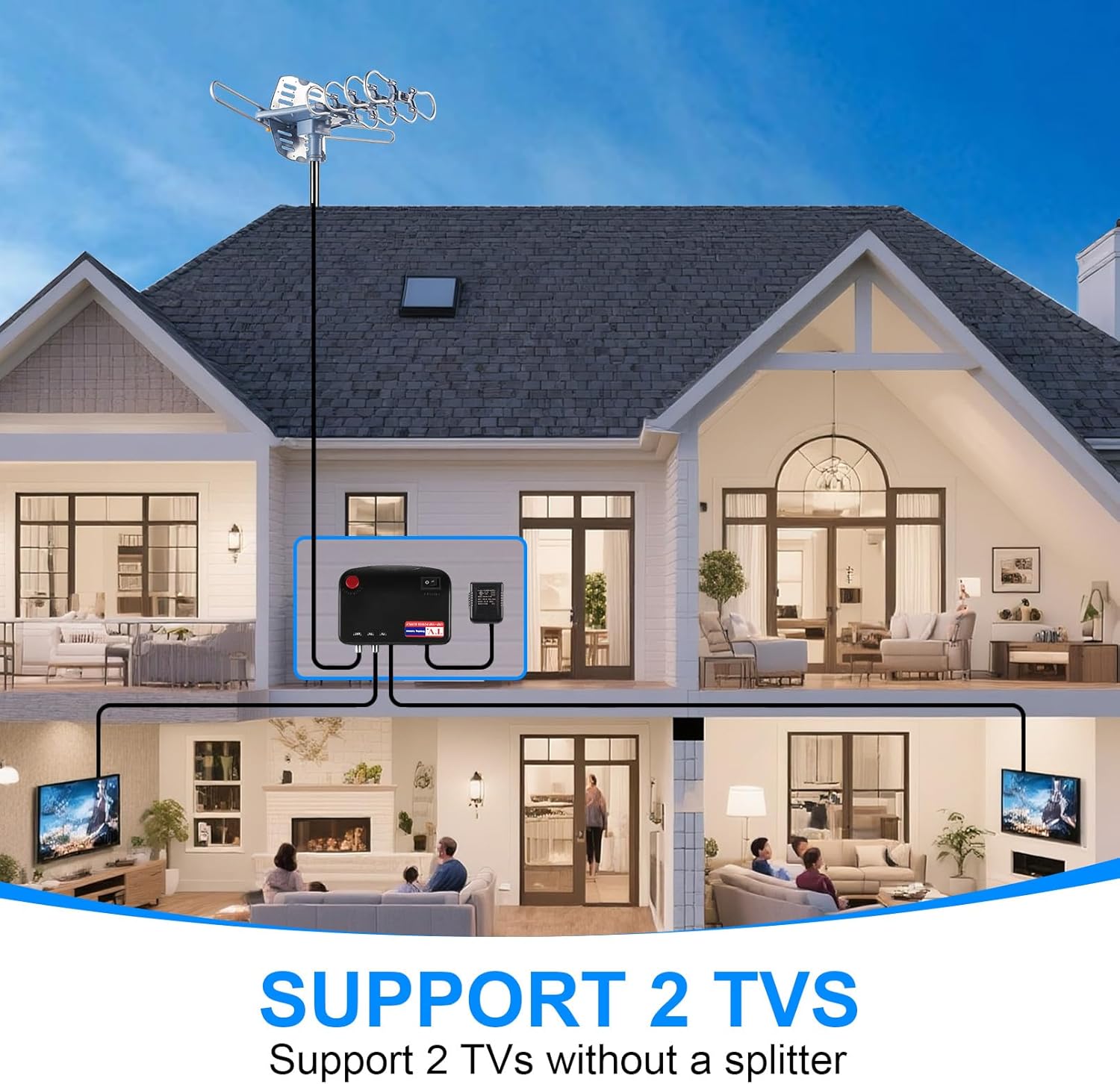
Figure 8: Antenna system supporting two televisions.
Maintenance
The Yeceny WA-2608 antenna is built with a lightning protection system and a durable structure to withstand various outdoor weather conditions. Regular maintenance is minimal but includes:
- Periodically inspect the antenna and mounting hardware for any signs of wear, corrosion, or loosening.
- Check coaxial cable connections for tightness and ensure they are free from damage.
- Keep the antenna clear of debris, snow, or ice to maintain optimal performance.
Troubleshooting
| Problem | Possible Cause | Solution |
|---|---|---|
| No Signal / Poor Picture Quality | Incorrect antenna direction, loose cable connections, interference, distant broadcast towers. | Use remote to rotate antenna for optimal signal. Check all coaxial cable connections. Rescan channels on TV. Ensure antenna has clear line-of-sight. |
| Antenna Not Rotating | Power issue, remote control battery, motor malfunction. | Check power supply to control box. Ensure remote control batteries are fresh. Verify the yellow indicator light is not on (indicating power/cable issue). |
| Yellow Light on Control Box | Power supply issue, cable connection problem. | Check power adapter connection. Ensure coaxial cable from antenna to control box is securely connected and not damaged. |
Specifications
- Model: WA-2608
- Antenna Type: Digital Amplified Outdoor HD TV Antenna
- Frequency Range: UHF/VHF
- Rotation: 360-degree with remote control
- Max Range: Up to 200 Miles (Note: Actual range may vary based on terrain and obstructions)
- Output Support: Supports 2 TVs simultaneously
- Coaxial Cable: 60 Ft RG6 Coaxial Cable included
- Lightning Protection: Built-in system
- Color: Silvery
- Impedance: 75 Ohm
- Product Dimensions: 17"L x 3.9"W x 12.2"H
- Item Weight: 6.74 pounds
Warranty & Support
For warranty information and technical support, please refer to the contact details provided on the product packaging or visit the official Yeceny website. Keep your purchase receipt as proof of purchase for any warranty claims.


