DEWENWILS Mechanical Outdoor Pool Pump Timer
DEWENWILS Mechanical Outdoor Pool Pump Timer Instruction Manual
Model: Mechanical Outdoor Pool Pump Timer
1. Introduction
The DEWENWILS Mechanical Outdoor Pool Pump Timer is a heavy-duty, programmable switch designed for automating various outdoor and indoor applications such as pool pumps, water heaters, fountains, spas, and other equipment motors. This timer features a robust, waterproof design suitable for outdoor use and offers up to 96 ON/OFF settings within a 24-hour period, allowing for precise control in 15-minute intervals.

Image: The DEWENWILS Mechanical Outdoor Pool Pump Timer installed in an outdoor setting, connected to a pool pump system.
2. Safety Information
WARNING: To avoid fire, shock, or death, turn off power at the circuit breaker or disconnect switch before installing or servicing. All wiring must be done in accordance with national and local electrical codes. This device must be installed by a qualified electrician if you are not familiar with electrical wiring.
- Ensure the power supply matches the timer's voltage rating (120-277 VAC).
- Do not exceed the maximum load capacity of 40 Amp, 2HP.
- The timer is ETL listed for safety.
- The waterproof and well-sealed plastic shell is designed to prevent water and dust ingress. Ensure the cover is securely closed after installation and programming.
- Operating temperature range: -40°F to 140°F (-40°C to 60°C).
- Use copper wire AWG 8-18 suitable for the current load.
- Proper grounding is essential for safe operation.
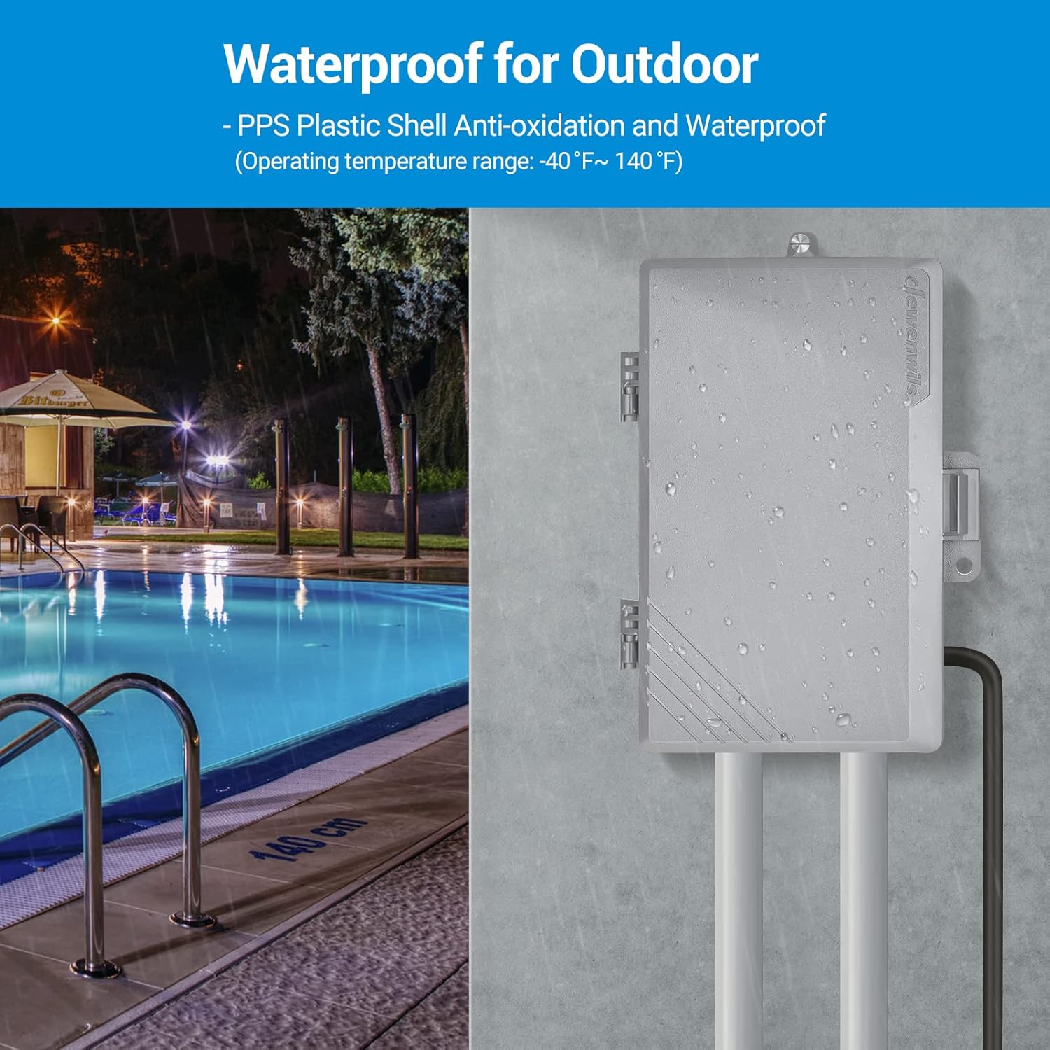
Image: The timer box demonstrating its waterproof PPS plastic shell, suitable for outdoor environments.
3. Product Overview and Components
The DEWENWILS Mechanical Outdoor Pool Pump Timer is designed for ease of use and durability. Key components are detailed below:

Image: An open view of the timer box, showcasing the mechanical dial, wiring terminals, and internal specifications label.

Image: Detailed diagram labeling the mechanical dial, POWER indicator, LOAD indicator, wiring screws, and knockouts (1/2'' and 3/4'' diameter) for conduit connections. The timer module is removable for easier wiring.
- Mechanical Dial: Used for setting ON/OFF times.
- POWER Indicator: Illuminates when power is supplied to the timer.
- LOAD Indicator: Illuminates when the connected load is active.
- Wiring Screws: Terminals for connecting power and load wires.
- Knockouts: Pre-punched holes (1/2'' and 3/4'' diameter) for easy conduit installation.
- Removable Timer Module: The internal timer mechanism can be detached from the box for convenient wiring and settings.
4. Specifications
| Feature | Specification |
|---|---|
| Input Voltage | 120-277 VAC, 60Hz |
| Max Load (Resistive) | 40A |
| Max Load (General Purpose) | 30A |
| Motor Load | 2HP (120-277 VAC) |
| Tungsten Load | 15A (120 VAC), 5A (250 VAC) |
| Ballast Load | 20A (120-277 VAC) |
| Pilot Duty | 800VA (120 VAC), 720VA (240 VAC) |
| Operating Temperature | -40°F to 140°F (-40°C to 60°C) |
| Material | Plastic |
| Certifications | ETL Listed |
5. Installation
Before beginning installation, ensure all power is disconnected at the main circuit breaker. The timer module can be removed from the housing to provide ample space for wiring. Follow the wiring diagrams carefully for your specific application.
5.1. 120VAC Wiring (Controlling One 120VAC Load)
For 120VAC applications, connect the wires as follows:
- Connect a jumper wire from the 'L' terminal to 'COM1'.
- Connect the Power Live Wire to 'COM1'.
- Connect the Power Neutral Wire and Load Neutral Wire to 'N'.
- Connect the Load Live Wire to 'NO1'.
- Connect the Power Ground Wire and Load Ground Wire to the Ground Screw.
5.2. 240VAC Wiring (Controlling One 240VAC Load)
For 240VAC applications, connect the wires as follows:
- Connect a jumper wire from the 'L' terminal to 'COM1'.
- Connect a jumper wire from the 'N' terminal to 'COM2'.
- Connect Power Live Wire 1 to 'COM1'.
- Connect Power Live Wire 2 to 'COM2'.
- Connect Load Neutral Wire 1 to 'NO1'.
- Connect Load Neutral Wire 2 to 'NO2'.
- Connect the Power Ground Wire and Load Ground Wire to the Ground Screw.
Video: This official DEWENWILS video demonstrates the wiring process for both 120VAC and 240VAC applications, showing step-by-step connections for power, load, and ground wires to the timer module.
6. Operating Instructions
The mechanical timer allows for easy programming of daily ON/OFF cycles.
- Set Current Time: Rotate the dial clockwise until the arrow indicates the current time.
- Program ON/OFF Times: The dial has pins around its circumference. Each pin represents 15 minutes.
- To set an ON period, push the pins outward for the desired duration.
- To set an OFF period, leave the pins in the inward position.
- Select Operating Mode: Use the manual switch to select the desired mode:
- "Clock" Position: The timer operates according to your programmed ON/OFF settings.
- "I" Position: Overrides the timer, keeping the device always ON.
- "O" Position: Overrides the timer, keeping the device always OFF.

Image: A close-up of the mechanical timer dial, illustrating how to push pins out for ON periods and keep them in for OFF periods. It also shows the manual switch positions for 'I' (ON), 'Clock' (Timer), and 'O' (OFF).

Image: The timer automating pool lighting, demonstrating its daily repeat scheduling capability for turning devices on and off at set times.
7. Maintenance
The DEWENWILS Pool Pump Timer requires minimal maintenance. To ensure optimal performance and longevity:
- Periodically inspect the timer for any signs of damage, wear, or loose connections.
- Keep the exterior of the timer clean. Use a soft, damp cloth to wipe away dust or dirt. Do not use abrasive cleaners or solvents.
- Ensure the cover is always securely latched to maintain its waterproof rating, especially in outdoor installations.
- If the timer is exposed to extreme weather conditions, consider additional protective measures.
8. Troubleshooting
If you encounter issues with your DEWENWILS Pool Pump Timer, refer to the following common troubleshooting steps:
| Problem | Possible Cause | Solution |
|---|---|---|
| Timer does not turn ON/OFF at programmed times. | Incorrect time setting; Pins not set correctly; Manual switch in wrong position; No power. | Verify current time is set accurately. Ensure pins are pushed out for ON times and in for OFF times. Check if the manual switch is in the "Clock" position. Confirm power supply to the timer. |
| Load does not turn ON/OFF. | Loose wiring connections; Overload; Faulty load device. | Turn off power and check all wiring connections for tightness. Ensure the load does not exceed the timer's maximum capacity. Test the load device independently to confirm it is functional. |
| Timer dial is stuck or not moving. | Debris obstructing the dial; Internal mechanical issue. | Ensure no foreign objects are interfering with the dial. If the issue persists, contact customer support. |
| Power indicator is off. | No power supply; Loose power connection. | Check the circuit breaker. Verify power connections to the timer are secure. |
9. Warranty and Support
DEWENWILS products are designed for reliability and performance. For warranty information, technical support, or any inquiries regarding your Mechanical Outdoor Pool Pump Timer, please contact DEWENWILS customer service directly. Refer to the product packaging or the official DEWENWILS website for the most current contact details.
Please have your product model and purchase date available when contacting support to facilitate a quicker resolution.
Related Documents - Mechanical Outdoor Pool Pump Timer
 |
ICM550-ENC Multi-Functional Timer: Specifications, Wiring, and Operation Guide Comprehensive guide for the ICM550-ENC Multi-Functional Timer by JCM Controls, detailing applications, technical specifications, contact ratings, environmental conditions, mechanical construction, timing functions, status LEDs, replacement compatibility, package contents, safety precautions, terminal block usage, wiring diagram interpretation, time setting, defrost timing, and mode selection. Includes a detailed mode switch selection table. |
 |
Intermatic ET8215C Electronic Timer Control - Technical Data Detailed technical specifications for the Intermatic ET8215C Electronic Timer Control, an astronomic 7-day, 2-circuit electronic control suitable for 120-277 VAC applications in an indoor metal enclosure. |
 |
Dewenwils Outdoor Mechanical Timer Box HOMT01A Installation and Operation Manual Comprehensive guide for the Dewenwils Outdoor Mechanical Timer Box (SKU: HOMT01A), covering installation instructions, specifications, wiring diagrams for various applications (120VAC, 240VAC, 277VAC), operating instructions, and a one-year limited warranty. |
 |
Dewenwils Indoor Mechanical Pin Timer Instruction Manual Instruction manual for the Dewenwils Indoor Mechanical Pin Timer, detailing operation, specifications, and warranty information. |
 |
Jewenwils Outdoor Wi-Fi Pool Timer HOWT01E: Installation and User Manual Comprehensive guide for the Jewenwils Outdoor Wi-Fi Pool Timer (Model HOWT01E, PTW01, PTW03). Includes specifications, installation instructions, app setup, timer functions, and safety information. |
 |
Tork P1101-2M 24-Hour Mechanical Time Switch Mechanism for Pool Panels Installation, programming, and operating instructions for the Tork P1101-2M 24-hour mechanical time switch mechanism, designed for pool panels. Features include 120V operation, 40A rating, and multiple operating modes. |
Ask a question about this manual
Ask about setup, troubleshooting, compatibility, parts, safety, or missing instructions. Manuals+ will review the question and use this page’s manual context to help answer it.