SATMW ST180 4000 Counts Digital Clamp
ST180 4000 Counts Digital Clamp Meter User Manual
Brand: SATMW | Model: ST180 4000 Counts Digital Clamp
1. Introduction
The ST180 4000 Counts Digital Clamp Meter is a versatile and reliable tool designed for accurate electrical measurements. This device combines the functions of an AC current multimeter, ammeter, voltage tester, and more, making it suitable for various automotive and household electrical troubleshooting tasks. Constructed from high-quality ABC plastic and featuring brass/PVC pen material, it offers excellent durability and drop protection.
Key features include automatic ranging for AC current up to 600A, resistance measurement up to 4000 ohms, temperature testing, and non-contact AC voltage detection. Its compact design and included carrying case ensure portability and convenience.
2. Product Overview

Figure 2.1: The ST180 Digital Clamp Meter, showcasing its compact design and red clamp jaw.

Figure 2.2: Detailed diagram of the ST180 Clamp Meter, highlighting its various components and controls. This includes the Jaw Open Trigger, LED Lighting, Function Dial, SEL/V button (function switch/flashlight), REL/RANGE button (data save/bright screen), H/BL button (switch range), LCD Backlight, Negative Black Test Lead Socket (COM), and Positive Red Test Lead Socket (VΩHz).
2.1. Components
- Clamp Jaw: Used for non-contact AC current measurement.
- Function Dial: Selects the measurement mode (e.g., AC Current, Voltage, Resistance, Diode, Continuity, NCV, Frequency).
- LCD Display: Shows measurement readings, units, and indicators.
- Buttons:
- SEL/V: Short press to switch functions within a mode (e.g., AC/DC voltage). Long press to activate flashlight.
- REL/RANGE: Short press for data hold. Long press for bright screen.
- H/BL: Short press to switch measurement range (manual/auto).
- Test Lead Sockets (COM, VΩHz): For connecting test leads for voltage, resistance, capacitance, diode, and continuity measurements.
- Flashlight: Integrated light for illuminating dark work areas.
3. Setup
3.1. Battery Installation
The ST180 Clamp Meter requires two AAA batteries for operation. To install or replace batteries:
- Ensure the meter is turned OFF.
- Locate the battery compartment cover on the back of the meter.
- Use a screwdriver to open the battery compartment.
- Insert two AAA batteries, observing the correct polarity (+/-) as indicated inside the compartment.
- Replace the battery compartment cover and secure it with the screw.
3.2. Connecting Test Leads
For measurements requiring test leads (e.g., voltage, resistance, continuity), connect them as follows:
- Insert the black test lead into the COM (common) input jack.
- Insert the red test lead into the VΩHz input jack.

Figure 3.1: The ST180 Clamp Meter shown with its included test leads and packaging, illustrating how the leads connect to the meter's input jacks.
4. Operating Instructions
Before any measurement, ensure the meter is set to the correct function and range. Always prioritize safety and follow proper electrical safety procedures.
4.1. Power On/Off
Rotate the Function Dial from the OFF position to any desired measurement mode to turn the meter ON. Rotate the dial back to OFF to power down the meter.
4.2. AC Current Measurement (Clamp Function)
This function allows non-contact measurement of AC current.
- Rotate the Function Dial to the 'A~' (AC Current) position.
- Press the Jaw Open Trigger to open the clamp jaw.
- Enclose a single conductor (wire) within the clamp jaw. Ensure the jaw is fully closed.
- Read the AC current value on the LCD display.
4.3. Voltage Measurement (AC/DC)
To measure AC or DC voltage:
- Connect the black test lead to the COM jack and the red test lead to the VΩHz jack.
- Rotate the Function Dial to the 'V~' (Voltage) position. The meter will typically auto-detect AC or DC. If not, press the SEL/V button to switch between AC and DC voltage.
- Touch the test probes to the points where voltage is to be measured (e.g., across a power source or component).
- Read the voltage value on the LCD display.
4.4. Resistance Measurement (Ω)
To measure resistance:
- Connect the black test lead to the COM jack and the red test lead to the VΩHz jack.
- Rotate the Function Dial to the 'Ω' (Resistance) position.
- Ensure the circuit or component is de-energized before measuring resistance.
- Touch the test probes across the component or circuit to be measured.
- Read the resistance value on the LCD display.
4.5. Continuity Test
To check for continuity (a complete circuit):
- Connect the black test lead to the COM jack and the red test lead to the VΩHz jack.
- Rotate the Function Dial to the 'Ω' (Resistance) position, then press SEL/V until the continuity symbol (a speaker icon) appears on the display.
- Touch the test probes to the two points of the circuit or component.
- If there is continuity (low resistance), the meter will emit an audible beep. The display will show a low resistance value.
4.6. Diode Test
To test a diode:
- Connect the black test lead to the COM jack and the red test lead to the VΩHz jack.
- Rotate the Function Dial to the 'Ω' (Resistance) position, then press SEL/V until the diode symbol (a triangle with a line) appears on the display.
- Touch the red probe to the anode and the black probe to the cathode of the diode. A forward voltage drop will be displayed.
- Reverse the probes. The display should show 'OL' (Open Line) for a good diode.
4.7. Capacitance Measurement (F)
To measure capacitance:
- Connect the black test lead to the COM jack and the red test lead to the VΩHz jack.
- Rotate the Function Dial to the 'Hz' (Frequency) position, then press SEL/V until the capacitance symbol (a capacitor icon) appears on the display.
- Discharge the capacitor before testing. Touch the test probes across the capacitor terminals.
- Read the capacitance value on the LCD display.
4.8. Frequency Measurement (Hz)
To measure frequency:
- Connect the black test lead to the COM jack and the red test lead to the VΩHz jack.
- Rotate the Function Dial to the 'Hz' (Frequency) position.
- Touch the test probes to the points where frequency is to be measured.
- Read the frequency value on the LCD display.
4.9. Non-Contact Voltage (NCV) Detection
The NCV function allows detection of AC voltage without direct contact, enhancing safety.
- Rotate the Function Dial to the 'NCV' position.
- Move the top part of the meter (near the clamp jaw) close to the conductor or outlet.
- The meter will emit an alarm sound and the screen will display '----' with increasing dashes as it gets closer to the AC voltage source. The closer the meter is to the voltage, the faster the alarm sounds.

Figure 4.1: The ST180 Clamp Meter performing NCV (Non-Contact Voltage) detection near an electrical outlet. The display shows '----' and an alarm sounds, indicating the presence of AC voltage.
4.10. Live Detection
This function helps identify live wires.
- Rotate the Function Dial to the 'Live' position.
- Insert the red test lead into the VΩHz jack.
- Touch the red probe to the wire or terminal to be tested.
- If it's a live wire (firewire), the screen will display 'EF' and emit a beep, and the LED will flash red. If it's a neutral line, the screen will display '----' and there will be no beep.
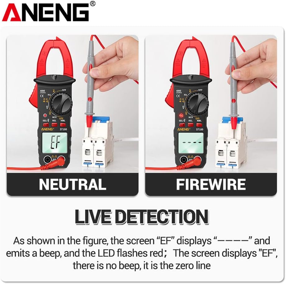
Figure 4.2: The ST180 Clamp Meter demonstrating Live Detection. On the left, testing a neutral line shows '----'. On the right, testing a live wire (firewire) shows 'EF' with an alarm and flashing LED.
4.11. Flashlight Function
The integrated flashlight helps illuminate dark work areas.
- Long press the SEL/V button to turn the flashlight ON or OFF.

Figure 4.3: The ST180 Clamp Meter with its built-in flashlight activated, providing illumination for working in dimly lit environments and helping to eliminate the risk of electric shock by improving visibility.
4.12. Data Hold
To freeze the current reading on the display:
- Short press the REL/RANGE button. The 'HOLD' indicator will appear on the display.
- Press the button again to release data hold.
4.13. Backlight
To activate the display backlight for better visibility in low light conditions:
- Long press the REL/RANGE button.
- Long press again to turn off the backlight.
5. Maintenance
5.1. Cleaning
To maintain the meter's performance and appearance:
- Wipe the casing with a damp cloth and mild detergent. Do not use abrasives or solvents.
- Ensure the meter is completely dry before storage or next use.
5.2. Battery Replacement
When the low battery symbol appears on the display, replace the batteries as described in Section 3.1. Prompt battery replacement ensures accurate readings and proper operation.
5.3. Storage
When not in use for extended periods:
- Turn the meter OFF.
- Remove the batteries to prevent leakage.
- Store the meter in its carrying case in a cool, dry place, away from direct sunlight and extreme temperatures.
6. Troubleshooting
This section addresses common issues you might encounter with your ST180 Clamp Meter.
| Problem | Possible Cause | Solution |
|---|---|---|
| Meter does not power on. | Dead or incorrectly installed batteries. | Check battery polarity or replace batteries. |
| Inaccurate readings. | Incorrect function/range selected; poor test lead connection; external interference. | Verify function dial setting; ensure test leads are securely connected; move away from strong electromagnetic fields. |
| No continuity beep. | Open circuit; incorrect mode. | Ensure circuit is complete; verify meter is in continuity mode. |
| NCV not detecting. | Too far from source; low voltage. | Move closer to the AC voltage source; ensure voltage is within detectable range. |
7. Specifications

Figure 7.1: A table detailing the function parameters of the ST180 Clamp Meter, including brand, model, max display, battery model, and weight. It also illustrates various functions like flashlight, Hz, data retention, diode, resistance, bright screen, Live, AC/DC voltage, on-off detection, capacitance, alternating current, NCV, and LED buzzer alarm.
| Parameter | Value |
|---|---|
| Brand | SATMW |
| Model | ST180 4000 Counts Digital Clamp |
| Maximum Display | 4000 Counts |
| Material | ABC Plastic |
| Pen Material | Brass/PVC |
| Battery Model | AAA * 2 |
| Product Size (L x W x H) | 14 x 4 x 1.5 cm (5.51 x 1.57 x 0.59 inches) |
| Total Line Length | 100 cm (39.3 inches) |
| Jaw Opening Size | 9.7 mm (0.38 inches) |
| Measurement Type | Ammeter, Multimeter |
| Color | Red |
| UPC | 739406705928 |

Figure 7.2: Dimensional drawing of the ST180 Clamp Meter, showing its height of 139.8mm (5.50in), width of 38mm (1.49in), and thickness of 10.4mm (0.41in).
8. Warranty and Support
For product support, technical assistance, or warranty inquiries, please contact the manufacturer or your point of purchase. Keep your purchase receipt as proof of purchase for any warranty claims.
While specific warranty details are not provided in this manual, standard consumer protection laws apply. Additionally, extended protection plans may be available for purchase from your retailer to cover the product beyond the manufacturer's standard warranty period.
Ask a question about this manual
Ask about setup, troubleshooting, compatibility, parts, safety, or missing instructions. Manuals+ will review the question and use this page’s manual context to help answer it.