1. Introduction
The Envistia MEGA2560 PRO MINI is a compact development board designed for embedded and stand-alone projects. It is a miniature version of the popular Mega 2560 microcontroller, offering identical functionalities in a smaller form factor. This board is based on the ATmega2560-16AU chip and features a CH340G USB-UART interface for connectivity.
Its compact size of 54mm x 38mm (2.1" x 1.5") makes it suitable for projects where space is a constraint. The board is compatible with the Arduino Mega 2560 ecosystem, allowing users to leverage existing libraries and development environments.
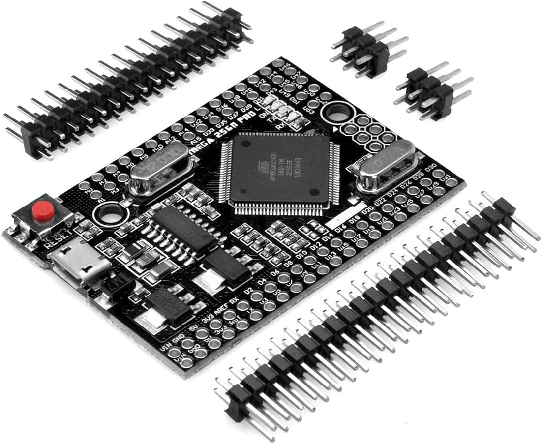
Figure 1: Envistia MEGA2560 PRO MINI Development Board with pin headers.
This image displays the Envistia MEGA2560 PRO MINI development board, a compact microcontroller unit. The board is black and features the central ATmega2560 chip, a micro-USB port, a reset button, and various pin headers for input/output. Several loose pin headers are also shown alongside the board, indicating they are included for assembly.
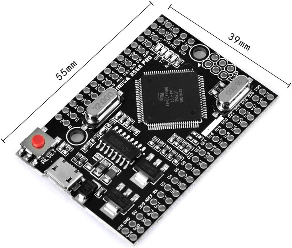
Figure 2: Board dimensions overview.
This image provides an overview of the board's physical dimensions, indicating a length of approximately 55mm and a width of 39mm, highlighting its compact design suitable for space-constrained projects.
2. Setup and Initial Configuration
2.1. Driver Installation
The MEGA2560 PRO MINI uses the CH340G USB-UART interface for communication with a computer. Before connecting the board, it may be necessary to install the CH340 driver on your operating system (Windows, macOS, Linux). Drivers are typically available from the CH340 manufacturer's website or common microcontroller development resources.
2.2. Connecting the Board
- Install Drivers: Ensure the CH340G drivers are correctly installed on your computer.
- Connect USB Cable: Connect one end of a micro-USB cable to the micro-USB port on the MEGA2560 PRO MINI board.
- Connect to Computer: Connect the other end of the micro-USB cable to an available USB port on your computer. The board should power on, indicated by an onboard LED.
- IDE Configuration: Open your preferred development environment (e.g., Arduino IDE). Select "Arduino Mega 2560" as the board type and choose the correct COM port associated with the CH340G.

Figure 3: Angled view highlighting the micro-USB connector and reset button.
This image provides an angled perspective of the Envistia MEGA2560 PRO MINI board. It clearly shows the micro-USB port on the left side, which is used for both power and data communication. The red reset button is also visible near the USB port.
2.3. Powering the Board
The board can be powered in two ways:
- Micro-USB Connector: Directly via the micro-USB cable connected to a computer or a 5V USB power adapter.
- Vin and GND Pins: Via the corresponding Vin and GND contacts on the board. The onboard voltage regulator accepts a recommended input voltage range of 6V to 9V DC. While the regulator can handle up to 18V, exceeding 9V is not recommended due to potential overheating and device damage.
The maximum current output for the 5V and 3.3V pins is 800mA each.
3. Operation and Programming
3.1. Basic Programming
The Envistia MEGA2560 PRO MINI is fully compatible with the Arduino IDE. You can write and upload sketches (programs) to the board using the standard Arduino programming language (based on C/C++).
- Write Code: Develop your program in the Arduino IDE.
- Select Board: Go to Tools > Board and select "Arduino Mega or Mega 2560".
- Select Port: Go to Tools > Port and select the serial port corresponding to your CH340G (e.g., COMx on Windows, /dev/ttyUSBx on Linux, /dev/cu.wchusbserialxxxx on macOS).
- Upload Sketch: Click the "Upload" button in the Arduino IDE to compile and transfer your sketch to the board.
3.2. Pinout Diagram
Understanding the pinout is crucial for connecting external components and sensors. The board provides 54 digital I/O pins and 16 analog input pins.

Figure 4: Detailed Pinout Diagram.
This image presents a comprehensive pinout diagram for the MEGA2560 PRO MINI board. It illustrates the location and function of each pin, including digital I/O, analog inputs, power pins (Vin, GND, 5V, 3.3V), and communication interfaces. This diagram is essential for connecting sensors, actuators, and other modules correctly.

Figure 5: Bottom view with pin labels.
This image shows the bottom side of the MEGA2560 PRO MINI board, clearly displaying the labels for various pins. This view is helpful for identifying pin functions when the board is mounted or when using custom headers. It includes labels for power input, voltage outputs, and various digital and analog pins.
4. Specifications
| Feature | Specification |
|---|---|
| Microcontroller | ATmega2560 |
| USB-UART Converter | CH340G |
| Clock Frequency | 16 MHz |
| Operating Voltage | 5V |
| Input Voltage (Recommended) | 6V to 9V DC (via Vin pin) |
| Input Voltage (Maximum) | 18V (not recommended to exceed 9V) |
| Digital I/O Pins | 54 |
| Analog Input Pins | 16 |
| Flash Memory | 256 KB (8 KB used by bootloader) |
| SRAM | 8 KB |
| EEPROM | 4 KB |
| DC Current per I/O Pin | 20 mA |
| DC Current for 3.3V Pin | 800 mA (maximum) |
| DC Current for 5V Pin | 800 mA (maximum) |
| Dimensions (L x W) | 54mm x 38mm (2.13" x 1.5") |
| Weight | 0.8 ounces |
| Operating Temperature | -40°C to +85°C |

Figure 6: Technical drawing with detailed dimensions.
This technical drawing provides precise measurements of the MEGA2560 PRO MINI board, including its overall length (54.00mm) and width (38.00mm), as well as the spacing of various components and mounting holes. This information is critical for integrating the board into custom enclosures or PCB designs.
5. Maintenance
The Envistia MEGA2560 PRO MINI is a robust electronic component designed for long-term use. Minimal maintenance is required.
- Keep Clean: Ensure the board is free from dust, dirt, and moisture. Use a soft, dry brush or compressed air for cleaning.
- Handle with Care: Avoid static discharge by handling the board on an anti-static mat or by grounding yourself. Do not apply excessive force to components or pins.
- Storage: Store the board in a dry, cool environment, preferably in an anti-static bag, when not in use.
- Power Supply: Always use a stable and appropriate power supply within the recommended voltage range to prevent damage.
6. Troubleshooting
If you encounter issues with your MEGA2560 PRO MINI board, consider the following common troubleshooting steps:
- Board Not Detected:
- Verify CH340G drivers are correctly installed.
- Try a different micro-USB cable.
- Test with a different USB port on your computer.
- Ensure the board is properly powered.
- Upload Errors:
- Confirm "Arduino Mega or Mega 2560" is selected under Tools > Board.
- Ensure the correct COM port is selected under Tools > Port.
- Check for syntax errors in your code.
- Disconnect any external components that might interfere with serial communication during upload.
- Unexpected Behavior:
- Double-check your wiring connections.
- Verify that external components are powered correctly and within the board's current limits.
- Review your code logic for errors.
- Ensure power supply is stable and sufficient.
- Overheating:
- Reduce input voltage if exceeding the recommended 9V.
- Ensure no short circuits are present.
- Reduce current draw from 5V/3.3V pins if exceeding 800mA.
7. Warranty and Support
For specific warranty information and technical support regarding your Envistia MEGA2560 PRO MINI Development Board, please refer to the official Envistia website or contact their customer service directly. Support resources often include FAQs, forums, and contact details for technical assistance.
Manufacturer: Envistia


