1. Introduction
This manual provides detailed instructions for the installation, operation, and maintenance of the Walfront HF020-7X1T1M Stepper Motor Motion Controller Module. This module is designed for precise control of stepper motors in various industrial automation applications.
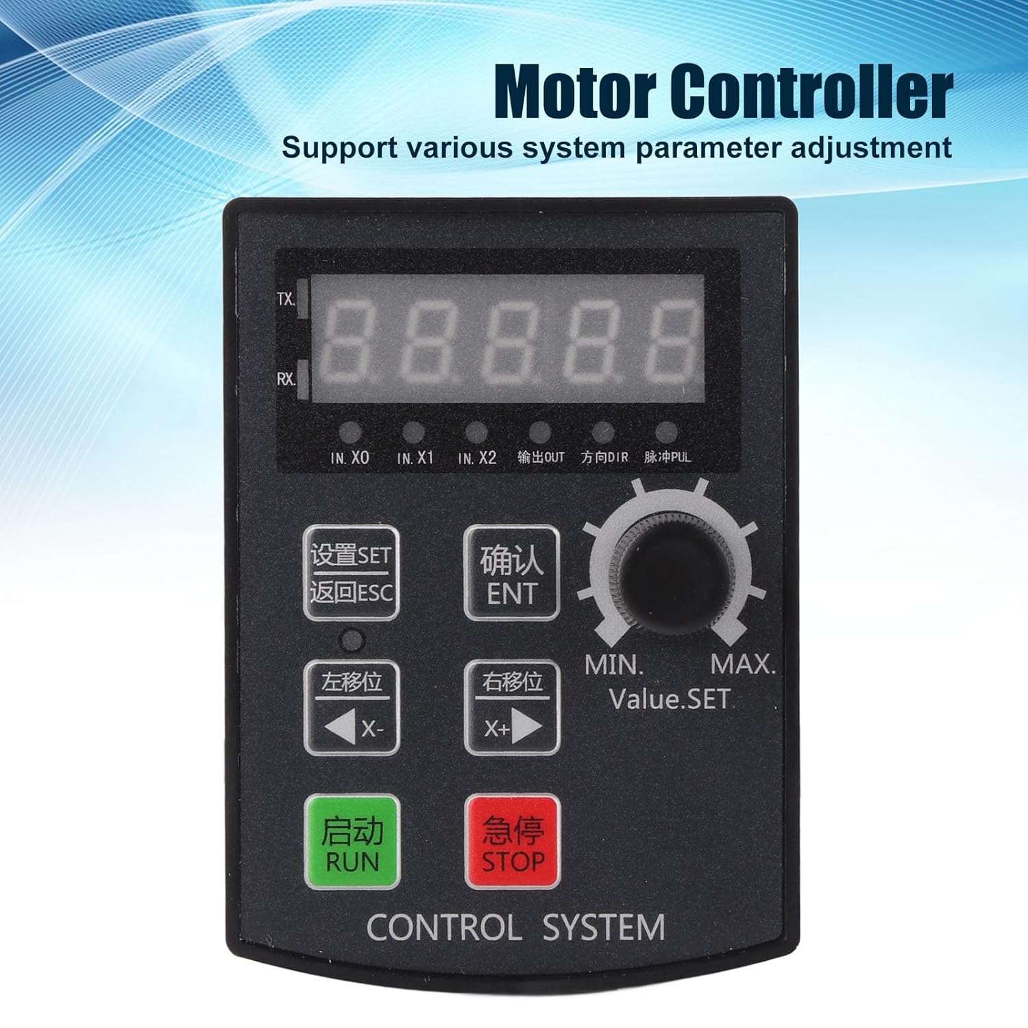
Figure 1: Front view of the Walfront HF020-7X1T1M Stepper Motor Motion Controller Module, showing the 5-digit display and control buttons.
2. Key Features
- Parameter Control: Supports precise positioning, angle, and revolution control, along with various system parameter adjustments.
- Debugging Convenience: Allows for manual motor movement, simplifying the debugging process.
- Wide Application: Suitable for industrial automation control, small machinery and equipment, automatic painting systems, and rotary indexing tools.
- High Pulse Frequency: Operates with a motor pulse frequency of 85 KHz.
- Driver Compatibility: The 24V motor pulse voltage collector can be directly connected to 5-24V drivers.
- Clear Display: Features a 5-digit digital screen with a high-brightness digital tube for clear information display and positive/negative limit communication.
3. Specifications
| Parameter | Value |
|---|---|
| Product Model | HF020-7X1T1M |
| Material | ABS |
| Operating Voltage | DC 12-24V |
| Hole Size | Approx. 92 x 69.8 mm / 3.62 x 2.75 inches |
| Operating Environment | -5℃ to 60℃ (non-condensing) |
| Motor Pulse Frequency | 85 KHz |
| Motor Pulse Voltage | 24V collector (directly connectable to 5-24V driver) |
| Display Structure | 5-digit, high-brightness digital tube |
| Outputs | 2 outputs (0V output voltage) |
| Inputs | 7 inputs (0V as valid signal) |
| Package Dimensions | 15.1 x 10.4 x 4.2 cm |
| Weight | 120 grams |
| Country of Origin | China |
4. Setup and Installation
Proper installation and wiring are crucial for the safe and effective operation of the controller module. Ensure all connections are secure and follow electrical safety guidelines.
4.1 Physical Installation
The module is designed for panel mounting. Cut an opening of approximately 92 x 69.8 mm (3.62 x 2.75 inches) in your control panel. Insert the module and secure it using the provided mounting hardware.

Figure 2: Top view of the controller module, showing the removable green terminal blocks for wiring connections.
4.2 Wiring Connections
Connect the power supply, motor driver, and input/output signals to the corresponding terminal blocks on the module. The module operates on DC 12-24V. The motor pulse voltage collector is 24V and can be directly connected to 5-24V drivers. Ensure correct polarity for the power supply.
- Power Input: Connect DC 12-24V to the designated power terminals.
- Motor Driver Connection: Connect the pulse (PUL) and direction (DIR) signals to your stepper motor driver. The module provides 85 KHz pulse frequency.
- Inputs (IN.X0, IN.X1, IN.X2, etc.): The module has 7 inputs. A 0V signal is considered valid for these inputs.
- Outputs: The module provides 2 outputs with 0V output voltage.

Figure 3: Angled view of the module's rear, highlighting the terminal blocks for input, output, and power connections.
5. Operating Instructions
The HF020-7X1T1M controller features a user-friendly interface with a 5-digit display and dedicated buttons for various functions.

Figure 4: Close-up of the control panel, showing the display, rotary encoder, and function buttons for setting parameters and controlling motor movement.
5.1 Control Panel Overview
- 5-Digit Display: Shows current values, parameters, and status.
- SET Button: Enters parameter setting mode.
- ESC Button: Exits current menu or cancels an operation.
- ENT (OK) Button: Confirms selections or enters sub-menus.
- X- (Left Shift) Button: Moves cursor left or decreases value.
- X+ (Right Shift) Button: Moves cursor right or increases value.
- RUN Button: Initiates motor operation.
- STOP Button: Halts motor operation.
- Rotary Encoder (Value.SET): Adjusts numerical values or navigates menus.
5.2 Parameter Adjustment
To adjust system parameters:
- Press the SET button to enter the parameter setting mode.
- Use the Rotary Encoder or X- / X+ buttons to navigate through parameters.
- Press ENT to select a parameter for editing.
- Adjust the value using the Rotary Encoder or X- / X+ buttons.
- Press ENT to confirm the new value.
- Press ESC to exit the parameter setting mode.
5.3 Manual Motor Movement
For debugging or precise manual control, the module supports manual motor movement:
- Ensure the motor is connected and powered.
- Use the X- and X+ buttons to manually jog the motor in the desired direction.
- The speed of manual movement may be adjustable in parameters.
6. Maintenance
The Walfront HF020-7X1T1M module is designed for durability and requires minimal maintenance. Adhering to these guidelines will ensure its longevity and reliable performance.
- Cleaning: Keep the module clean and free from dust and debris. Use a soft, dry cloth for cleaning. Avoid using liquid cleaners or solvents.
- Environmental Conditions: Operate the module within the specified temperature range of -5℃ to 60℃ and in a non-condensing environment. Protect it from excessive moisture, direct sunlight, and corrosive substances.
- Connection Checks: Periodically inspect all wiring connections to ensure they are secure and free from corrosion or damage.
- Firmware Updates: Check the manufacturer's website for any available firmware updates. Follow the provided instructions carefully if performing an update.
7. Troubleshooting
This section provides guidance for common issues you might encounter with the HF020-7X1T1M module.
7.1 Controller Version Viewing Method
To view the controller's version number:
- Press and hold the ENT (OK) key.
- While holding ENT, power on the module.
- The version number will be displayed on the screen, for example, [21.100].
- The first two digits (e.g., 21) indicate the year (e.g., 2021).
- The next two digits (e.g., 10) indicate the month (e.g., October).
- The last digit (e.g., 0) indicates the version without RS485 communication, while 8 indicates a version with RS485 communication.
7.2 Common Issues
- No Power: Check the DC 12-24V power supply connection and ensure correct polarity. Verify the power source is active.
- Motor Not Moving: Verify motor driver connections (PUL, DIR), power to the motor driver, and motor wiring. Check if the RUN command has been issued and if parameters are set correctly.
- Incorrect Movement: Review the direction and step parameters. Ensure the motor driver is configured correctly for the stepper motor.
- Display Errors: If the display shows unusual characters or no information, try restarting the module. If the issue persists, contact support.
8. Warranty and Support
For warranty information, technical support, or service inquiries, please refer to the documentation provided with your purchase or contact Walfront customer service through their official channels. Keep your purchase receipt for warranty claims.
