1. Introduction
The LILLIPUT AVMATRIX SD2080 is a versatile 2x8 SDI/HDMI Splitter and Converter designed for professional video applications. It automatically detects input signals, supporting both HDMI and 3G-SDI, and provides simultaneous distribution and conversion to four 3G-SDI and four HDMI outputs. This device is ideal for scenarios requiring signal splitting, format conversion, and extended cable runs with SDI equalization and re-clocking capabilities.
This manual provides essential information for the proper installation, operation, and maintenance of your SD2080 unit. Please read it thoroughly before use.
2. Safety Information
- Ensure the power supply voltage matches the device's requirements.
- Do not expose the unit to rain, moisture, or extreme temperatures.
- Avoid placing the unit near heat sources or in direct sunlight.
- Do not open the casing; refer all servicing to qualified personnel.
- Disconnect power before cleaning or moving the unit.
- Use only the provided power adapter.
3. Package Contents
Verify that all items are present in the package:
- AVMATRIX SD2080 Main Unit
- Power Adapter (USB and threaded locking DC)
- Detachable Mounting Brackets (2x)
- User Manual (this document)
4. Product Features

Image Description: This image displays a diagram highlighting the key features of the AVMATRIX SD2080. It shows icons and text indicating 2x8 distribution, HDMI/SDI conversion, support for up to 1080p60, SDI equalization, and clock recovery.
- Auto-detected input: 1×HDMI / 1×3G-SDI
- Pass-through output: 4×3G-SDI, 4×HDMI
- Distributes and converts between SDI & HDMI signals.
- SDI with equalization and re-clocking for reliable signal transmission over long distances.
- Input and output support up to 1080p60 resolution.
- Easy input signal switching via DIP switches.
- USB and threaded locking DC power supply for secure connection.
- Detachable bracket design for flexible wall mounting options.
5. Product Overview
5.1 Front Panel

Image Description: This image shows the front panel of the AVMATRIX SD2080. From left to right, it features an HDMI input port, an SDI input port, and four SDI output ports (SDI OUT 1-4). Small indicator lights are visible next to the input ports.
- HDMI IN: HDMI input port.
- SDI IN: 3G-SDI input port.
- SDI OUT 1-4: Four 3G-SDI output ports.
- Indicator Lights: Signal status indicators for inputs.
5.2 Rear Panel
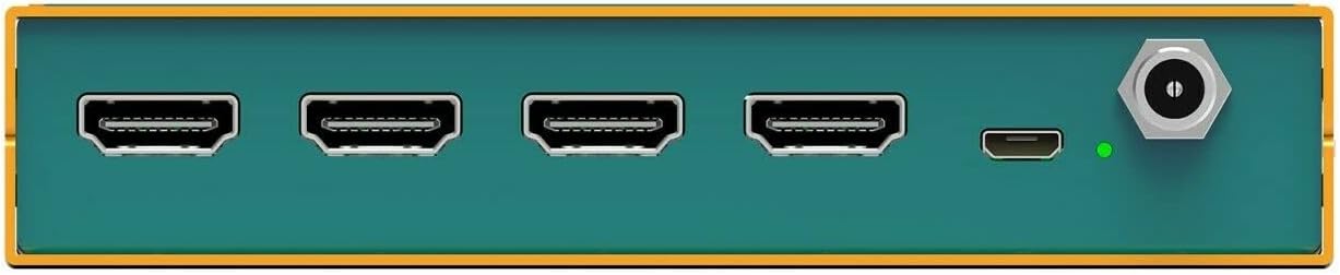
Image Description: This image displays the rear panel of the AVMATRIX SD2080. It features four HDMI output ports (HDMI OUT 1-4), a USB port, and a threaded locking DC power input port. A power indicator light is also visible.
- HDMI OUT 1-4: Four HDMI output ports.
- USB: USB port for potential firmware updates or control.
- POWER: Threaded locking DC power input.
- Power Indicator: Indicates power status.
5.3 Top Panel and DIP Switches

Image Description: This image provides a close-up view of the DIP switches located on the side of the AVMATRIX SD2080 unit. There are four individual switches labeled 1, 2, 3, and 4, with an "ON" position indicated in red. These switches are used for input selection.
- DIP Switches (1-4): Used to select the active input source (HDMI or SDI). Refer to the "Operating Instructions" section for detailed configuration.
6. Setup and Installation
6.1 Physical Installation
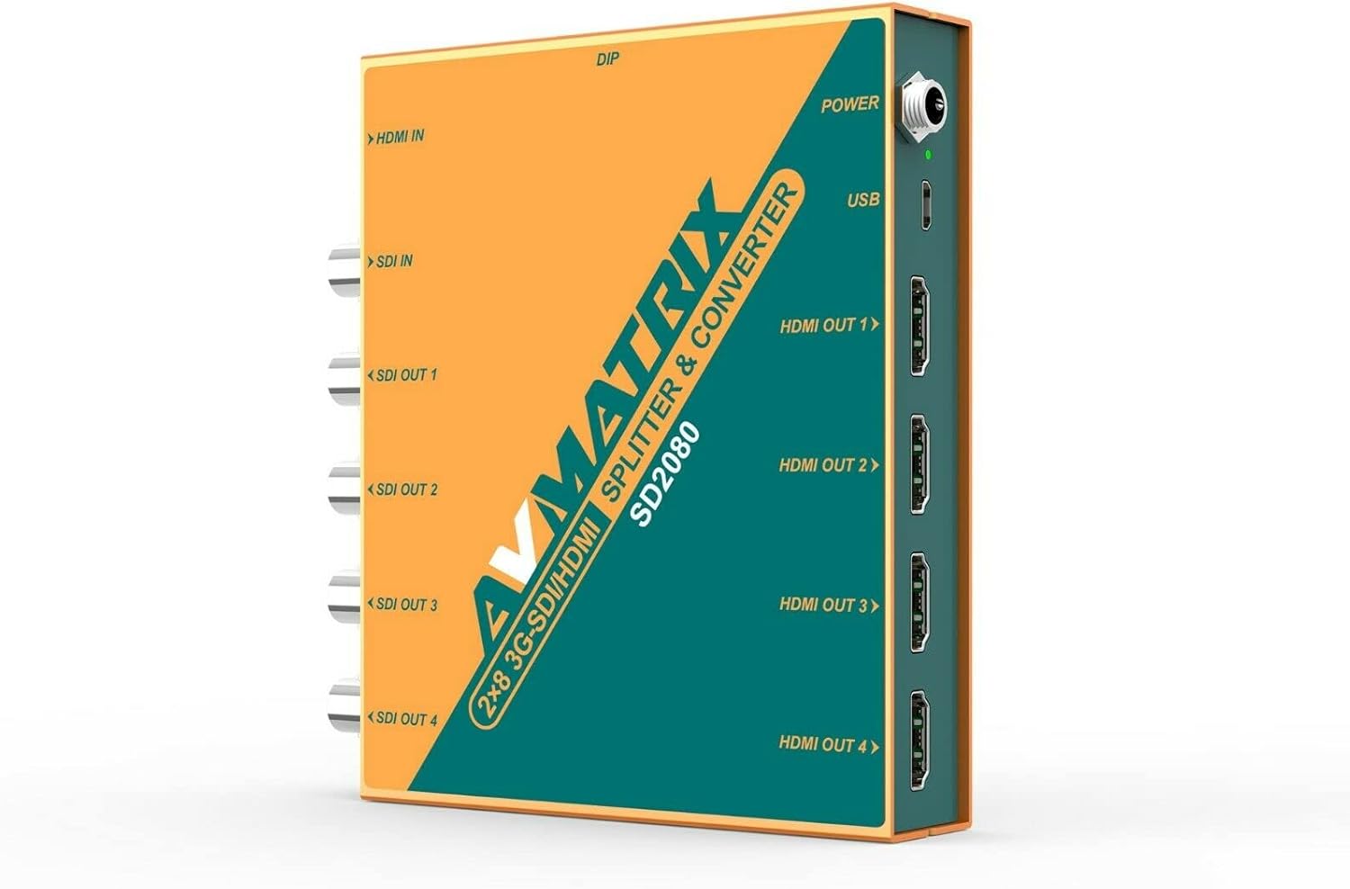
Image Description: This image shows the AVMATRIX SD2080 unit with its detachable mounting brackets attached. The brackets are designed for wall mounting, providing flexible installation options.
The SD2080 comes with detachable mounting brackets for flexible installation. Attach the brackets to the sides of the unit using the provided screws. Once attached, the unit can be securely mounted to a wall or other flat surface.
6.2 Connecting Devices

Image Description: This diagram illustrates typical connection scenarios for the AVMATRIX SD2080. It shows various input sources like a Video Switcher (HDMI In) and PTZ Camera (SDI In) connecting to the SD2080. The outputs are then shown connecting to devices such as a TV, LED Wall, Recorder, and Projector via HDMI Out and SDI Out ports.
- Input Connection: Connect your HDMI source (e.g., video switcher, computer) to the HDMI IN port. Connect your 3G-SDI source (e.g., PTZ camera, SDI encoder) to the SDI IN port. The unit will auto-detect the active input.
- Output Connection: Connect your display devices (e.g., monitors, TVs, projectors) to the HDMI OUT 1-4 ports. Connect your SDI receiving devices (e.g., recorders, SDI monitors) to the SDI OUT 1-4 ports.
- Power Connection: Connect the provided power adapter to the POWER input on the rear panel. Ensure the threaded locking connector is securely fastened.
7. Operating Instructions
7.1 Power On/Off
Once all connections are made, connect the power adapter to an electrical outlet. The power indicator light on the rear panel will illuminate, indicating the unit is powered on. There is no separate power button; the unit powers on automatically when connected to power.
7.2 Input Selection using DIP Switches
The AVMATRIX SD2080 features DIP switches on its side panel to select the active input source. The unit supports auto-detection, but manual selection can be enforced if needed.
Image Description: This image shows the four DIP switches (1-4) on the side of the AVMATRIX SD2080. The switches are currently set to an "ON" position for switches 1, 2, 3, and 4. This configuration determines the input source selection.
Refer to the following table for DIP switch configurations:
| DIP Switch Setting | Input Source | Description |
|---|---|---|
| All OFF | Auto-detect | The unit automatically detects and uses the first active input (HDMI or SDI). |
| Switch 1 ON, others OFF | HDMI IN | Forces the unit to use the HDMI input. |
| Switch 2 ON, others OFF | SDI IN | Forces the unit to use the SDI input. |
| Other combinations | Reserved / Auto-detect | For optimal performance, use only the specified settings for forced input. |
Note: Always power off the unit before changing DIP switch settings to ensure proper application of the new configuration.
7.3 Signal Distribution and Conversion
Once an input signal is detected and selected, the SD2080 will simultaneously distribute the signal to all four SDI outputs and convert/distribute it to all four HDMI outputs. The SDI outputs feature equalization and re-clocking to maintain signal integrity over longer cable runs.
8. Maintenance
- Cleaning: Use a soft, dry cloth to clean the unit. Do not use liquid or aerosol cleaners.
- Storage: Store the unit in a cool, dry place away from direct sunlight and extreme temperatures when not in use for extended periods.
- Ventilation: Ensure proper ventilation around the unit to prevent overheating. Do not block any ventilation openings.
9. Troubleshooting
| Problem | Possible Cause | Solution |
|---|---|---|
| No video output |
|
|
| Intermittent signal |
|
|
| DIP switch changes not taking effect | Unit not power cycled after changing DIP switches. | Disconnect and reconnect power after making DIP switch changes. |
10. Specifications
Image Description: This image includes a detailed technical specification table for the AVMATRIX SD2080, covering inputs, outputs, SDI video rate, compliance, color space, format support for SDI and HDMI, dimensions, weight, power, and environmental conditions. It also shows a diagram of the unit's dimensions and port layout.
| Category | Specification |
|---|---|
| Inputs | 1×HDMI (Type A), 1×3G-SDI |
| Outputs | 4×HDMI, 4×3G-SDI |
| SDI Video Rate | SD/HD/3G-SDI |
| SDI Compliance | SMPTE 259M, SMPTE 292M, SMPTE 424M |
| SDI Color Space | YUV 4:2:2 |
| Input/Output Support | Up to 1080p60 |
| Power Connector | DC 12V (USB and threaded locking) |
| Current | 600mA |
| Voltage Range | 6-28V |
| Power Consumption | 6.5W |
| Operating Temperature | -20°C ~ 60°C |
| Storage Temperature | -30°C ~ 70°C |
| Relative Humidity | 0% ~ 90% non-condensing |
| Dimensions (LWD) | 104mm x 125.5mm x 24.5mm (approx. 4.1 x 4.9 x 1.0 inches) |
| Weight | 485g (approx. 1.07 lbs) |
11. Support and Contact
For technical support, warranty inquiries, or further assistance, please contact LILLIPUT customer service. Refer to the official LILLIPUT website for the most up-to-date contact information.
Website: www.avmatrixusa.com
Email: Sales@avmatrixusa.com
Phone: 1-888-608-3088