1. Introduction
The JHEMCU VTX20-600 is a compact and versatile 5.8GHz video transmitter (VTX) designed for FPV (First Person View) racing drones and other remote-controlled aircraft. It features adjustable transmitting power levels from PitMode to 600mW, 40 channels, and a wide input voltage range, making it suitable for various FPV applications. This manual provides essential information for the proper installation, operation, and maintenance of your VTX20-600.

Image 1.1: JHEMCU VTX20-600 FPV Transmitter with included antenna and wiring harness.
2. Safety Precautions
- Always ensure correct polarity when connecting power to the VTX. Incorrect wiring can cause permanent damage.
- Never power on the VTX without an antenna connected. Operating without an antenna can severely damage the transmitter module.
- Ensure adequate airflow around the VTX, especially when operating at higher power levels, to prevent overheating.
- Adhere to local regulations regarding FPV transmission frequencies and power levels.
- Keep the device away from water and moisture.
3. Product Overview and Specifications
The VTX20-600 is designed for robust performance in FPV systems. Its compact size and adjustable power output make it a flexible choice for various drone builds.
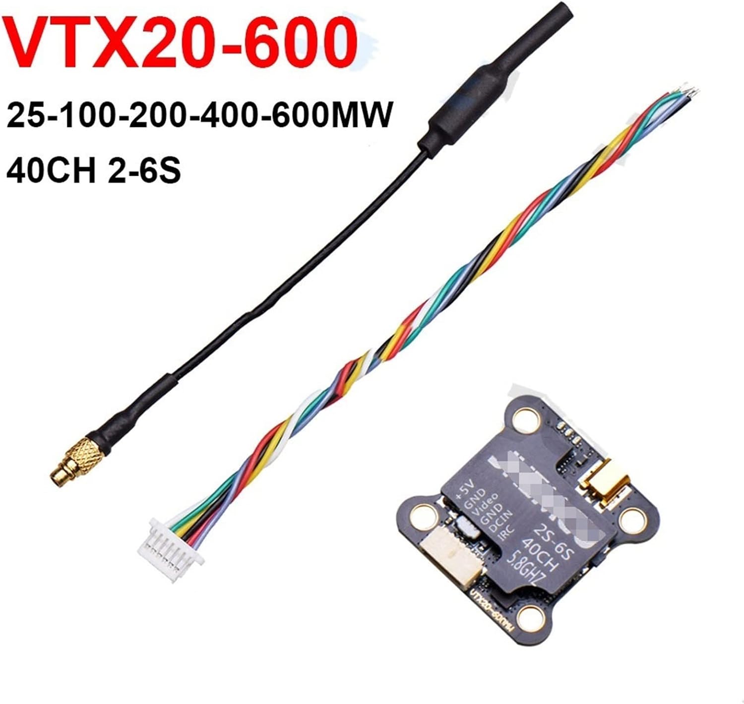
Image 3.1: Detailed view of the VTX20-600 module with its components.
Technical Specifications:
- Input Voltage: 7-26V (2S-6S LiPo compatible)
- Output Voltage/Current: 5V/1A (for camera power)
- Number of Channels: 40CH
- Transmitting Power: PIT/25mW/100mW/200mW/400mW/600mW (Adjustable)
- Frequency: 5.8GHz
- Dimensions: 27mm x 27mm
- Mounting Hole Pattern: 20mm x 20mm
4. Setup and Wiring
Proper wiring is crucial for the functionality and longevity of your VTX. Refer to the pinout diagram below for correct connections.

Image 4.1: Pinout diagram for the VTX20-600 module.
Wiring Connections:
- +5V: Connect to the 5V power input of your FPV camera. This output provides regulated 5V power from the VTX.
- GND (Camera): Connect to the ground of your FPV camera.
- Video: Connect to the video output of your FPV camera.
- GND (Power): Connect to the main ground of your flight controller or power distribution board (PDB).
- DCIN: Connect to the main battery voltage (7-26V, 2S-6S LiPo). Ensure correct polarity.
- IRC: Connect to a UART TX pad on your flight controller for SmartAudio/IRC Tramp control. This allows OSD (On-Screen Display) control of VTX settings.
Antenna Connection:
Carefully screw the provided 5.8GHz antenna onto the VTX's SMA or U.FL connector. Ensure it is securely tightened but do not overtighten. Always connect the antenna before applying power to the VTX.

Image 4.2: Close-up of the VTX20-600 showing the connection pads and antenna port.
5. Operating Instructions
The VTX20-600 can be configured via a physical button or through SmartAudio/IRC Tramp protocol from your flight controller's OSD.
Button Control:
The VTX features a single button for manual configuration. An LED indicator will show the current status.

Image 5.1: Top view of the VTX20-600, highlighting the control button and LED.
- Short Press: Cycles through power levels (PIT/25mW/100mW/200mW/400mW/600mW). The LED will flash to indicate the selected power level.
- Long Press (3 seconds): Cycles through bands (A, B, E, F, R). The LED will flash to indicate the selected band.
- Very Long Press (5 seconds): Cycles through channels within the selected band. The LED will flash to indicate the selected channel.
Refer to the frequency table (usually provided with your flight controller's OSD or online resources) to match LED flashes to specific channels and bands.
SmartAudio/IRC Tramp Control:
For OSD control, ensure the IRC pin of the VTX is connected to a TX pad on your flight controller and configured correctly in Betaflight/INAV firmware. This allows you to change VTX settings (power, band, channel, PitMode) directly from your FPV goggles' OSD menu.
6. Maintenance
- Cleaning: Keep the VTX free from dust, dirt, and moisture. Use a soft, dry brush or compressed air for cleaning. Avoid using liquids.
- Heat Management: Ensure the VTX is mounted in a location with adequate airflow to dissipate heat, especially during prolonged operation at high power. Overheating can reduce performance and lifespan.
- Antenna Care: Regularly check the antenna connection for tightness and inspect the antenna for any damage. A damaged antenna can lead to poor video quality and VTX damage.
7. Troubleshooting
- No Video Signal:
- Check all wiring connections (power, ground, video) between the camera, VTX, and flight controller.
- Ensure the VTX has power and its LED indicator is active.
- Verify that your FPV goggles/receiver are on the correct band and channel.
- Confirm the antenna is securely connected to the VTX.
- Poor Video Quality (Static, Lines, Short Range):
- Check for interference from other electronic components (e.g., ESCs, motors). Try to separate the VTX from these components.
- Ensure the VTX power level is set appropriately for your flying environment.
- Inspect the VTX antenna and receiver antenna for damage. Try a different antenna if possible.
- Verify that the VTX is not overheating.
- VTX Overheating:
- Reduce the transmitting power level.
- Improve airflow around the VTX.
- Ensure the VTX is not in contact with other components that generate heat.
8. Warranty and Support
For warranty claims or technical support, please contact the retailer or manufacturer directly. Keep your proof of purchase for warranty validation. This manual is intended for informational purposes only, and specifications are subject to change without notice.