1. Introduction
This manual provides essential information for the proper installation, operation, and maintenance of the SIMPLEX 4098-5207 5-inch Sensor Base with Remote LED Output. Please read this manual thoroughly before attempting to install or operate the device. Retain this manual for future reference.
2. Product Description
The SIMPLEX 4098-5207 is a 5-inch sensor base designed for use with compatible SIMPLEX fire alarm sensors. It provides the necessary electrical connections for the sensor and includes terminals for a remote LED indicator, allowing for visual status indication at a distance from the sensor itself. This base is an integral component of a fire detection system, ensuring secure mounting and reliable electrical interface for the sensor head.
3. Safety Information
WARNING:
- Installation and wiring must be performed by qualified personnel in accordance with all local and national electrical codes and standards, including NFPA 72.
- Disconnect all power to the control panel before installing or servicing the sensor base. Failure to do so may result in electric shock, equipment damage, or improper operation.
- Ensure all connections are secure and correct to prevent system malfunctions.
- This device is part of a life safety system. Do not modify or tamper with the unit.
- Refer to the specific sensor head's manual for additional safety and installation instructions.
4. Package Contents
- 1 x SIMPLEX 4098-5207 5-inch Sensor Base
Note: Sensor head and remote LED indicator are sold separately.
5. Setup and Installation
The SIMPLEX 4098-5207 sensor base is designed for mounting to a standard electrical box. Follow these steps for proper installation:
- Power Disconnection: Ensure all power to the fire alarm control panel and associated circuits is disconnected before beginning installation.
- Mounting: Secure the sensor base to a compatible electrical box using the provided mounting screws. Ensure the base is firmly attached to the mounting surface.
- Wiring Connections:
- Connect the fire alarm circuit wiring to the designated terminals on the sensor base. Refer to the system wiring diagrams for correct polarity and connection points.
- If using a remote LED indicator, connect its wiring to the dedicated remote LED terminals on the base. Observe polarity.
- Ensure all wire insulation is stripped to the correct length and connections are tight to prevent shorts or intermittent operation.
- Sensor Head Installation: Once the base is wired and mounted, align the compatible SIMPLEX sensor head with the base and twist clockwise until it locks securely into place.
- Power Restoration and Testing: After installation, restore power to the fire alarm control panel. Perform system tests as per the control panel manufacturer's instructions and local codes to verify proper operation of the sensor and remote LED.
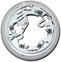
Figure 1: SIMPLEX 4098-5207 5-inch Sensor Base. This image shows the top view of the sensor base, highlighting the internal wiring terminals and mounting points for a compatible sensor head.
6. Operation
The SIMPLEX 4098-5207 sensor base itself does not have operational controls. Its function is to provide a secure mounting and electrical interface for a compatible SIMPLEX sensor head. The operational status (e.g., normal, alarm, trouble) is indicated by the LED on the sensor head and, if connected, by the remote LED indicator. Refer to the specific sensor head's manual for detailed operational characteristics and LED indications.
7. Maintenance
Regular maintenance is crucial for the reliable operation of any fire detection system component. For the SIMPLEX 4098-5207 sensor base:
- Visual Inspection: Periodically inspect the sensor base for any signs of physical damage, corrosion, or loose connections.
- Cleaning: If dust or debris accumulates on the base, gently clean it with a soft, dry cloth. Do not use abrasive cleaners or solvents.
- System Testing: Follow the recommended testing schedule for the entire fire alarm system as outlined in NFPA 72 and local codes. This includes functional testing of the sensor head mounted on the base.
8. Troubleshooting
Most issues related to the sensor base are typically associated with wiring or the sensor head itself. If you encounter problems:
- No Power/No LED Indication:
- Verify that power is supplied to the fire alarm circuit.
- Check all wiring connections at the base for looseness or incorrect polarity.
- Ensure the sensor head is properly seated and locked onto the base.
- Remote LED Not Functioning:
- Check the wiring connections for the remote LED at the base and at the LED unit itself.
- Verify the remote LED is compatible and correctly polarized.
- System Trouble/Fault:
- Consult the fire alarm control panel's manual for specific trouble codes.
- Inspect the sensor head for damage or malfunction.
- If issues persist, contact a qualified fire alarm technician.
9. Specifications
| Feature | Detail |
|---|---|
| Model Number | 4098-5207 |
| Part Number | S40985207 |
| Brand | SIMPLEX |
| Size | 5-inch diameter (approximate) |
| Compatibility | Compatible with SIMPLEX fire alarm sensor heads (refer to specific sensor documentation) |
| Features | Remote LED Output terminals |
| Power Source | System Powered (from fire alarm control panel) |
| UPC | 742779304148 |
10. Warranty and Support
For warranty information and technical support, please contact your authorized SIMPLEX distributor or the manufacturer directly. Keep your purchase receipt and product serial number (if applicable) handy when contacting support.
Manufacturer: SIMPLEX