S SIMDER MIG250
SSIMDER MIG250 Multi-Process Welder User Manual
Model: MIG250
1. Introduction
The SSIMDER MIG250 is a versatile 4-in-1 multi-process welding machine designed for various welding applications, including MMA (Stick), Lift TIG, Flux MIG, and Gas MIG. It features dual voltage compatibility (110V/220V) and IGBT control for stable arc performance. This manual provides essential information for safe and effective operation, setup, maintenance, and troubleshooting.

Figure 1: SSIMDER MIG250 Multi-Process Welder and Included Accessories.
The image displays the SSIMDER MIG250 welding machine along with its standard accessories, including the MIG gun, ground clamp, electrode holder, flux core wire, 220V to 110V adapter, 1.0mm K Wheel, and gas tube.
2. Key Features
- 4-in-1 Multi-Process Welding: Supports MMA (Stick), Lift TIG, Flux MIG, and Gas MIG welding modes.
- Dual Voltage Capability: Operates on both 110V and 220V input power, offering flexibility for different work environments.
- Synergistic Adjustment Function: Simplifies settings, making it user-friendly for both beginners and experienced welders.
- IGBT Inverter Technology: Ensures stable arc performance for smoother and deeper welds.
- Wire Compatibility: Applicable for 0.030"-0.035" MIG welding wire and 7018, 6010, 6013 Stick welding electrodes.
- Multiple Protection Mechanisms: Includes over-current, over-voltage, and over-heat automatic protection for enhanced safety and extended machine lifespan.
- Spacious Wire Compartment: Accommodates 2LBS/10LBS Flux Core Wire/Solid Wire spools.
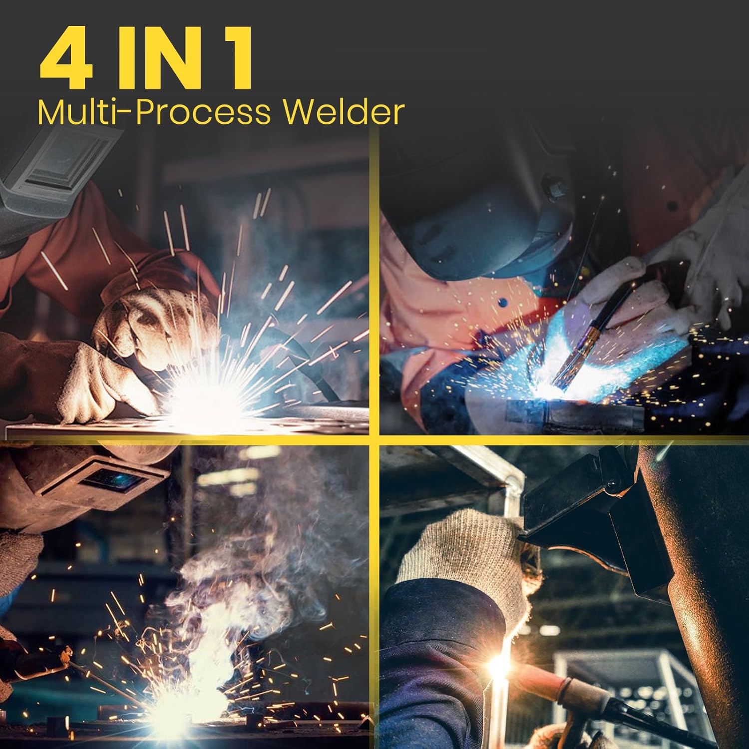
Figure 2: The 4-in-1 Multi-Process Capability of the Welder.
This image illustrates the four primary welding processes supported by the SSIMDER MIG250: MIG, TIG, Stick, and Flux Core welding, highlighting its versatility.
3. Setup and Connections
3.1 Power Connection
The MIG250 welder supports dual voltage input. Ensure the correct power source is used and the appropriate adapter is connected if necessary.

Figure 3: Dual Voltage Input (110V/220V).
The image shows the welder's capability to operate on both 110V for lightweight work and 220V for construction site work, with an adapter for 110V connection.
3.2 Wire Spool Installation
The machine is compatible with 2LBS and 10LBS flux core or solid wire spools. Open the side panel to access the wire feed mechanism and install the spool securely.

Figure 4: Wire Spool Installation (10LBS shown).
This image demonstrates the internal compartment of the welder, showing how a 10LBS welding wire spool is installed onto the spindle and fed into the wire feeder.
3.3 Front Panel Overview and Connections
Familiarize yourself with the front panel controls and connection points for different welding modes.
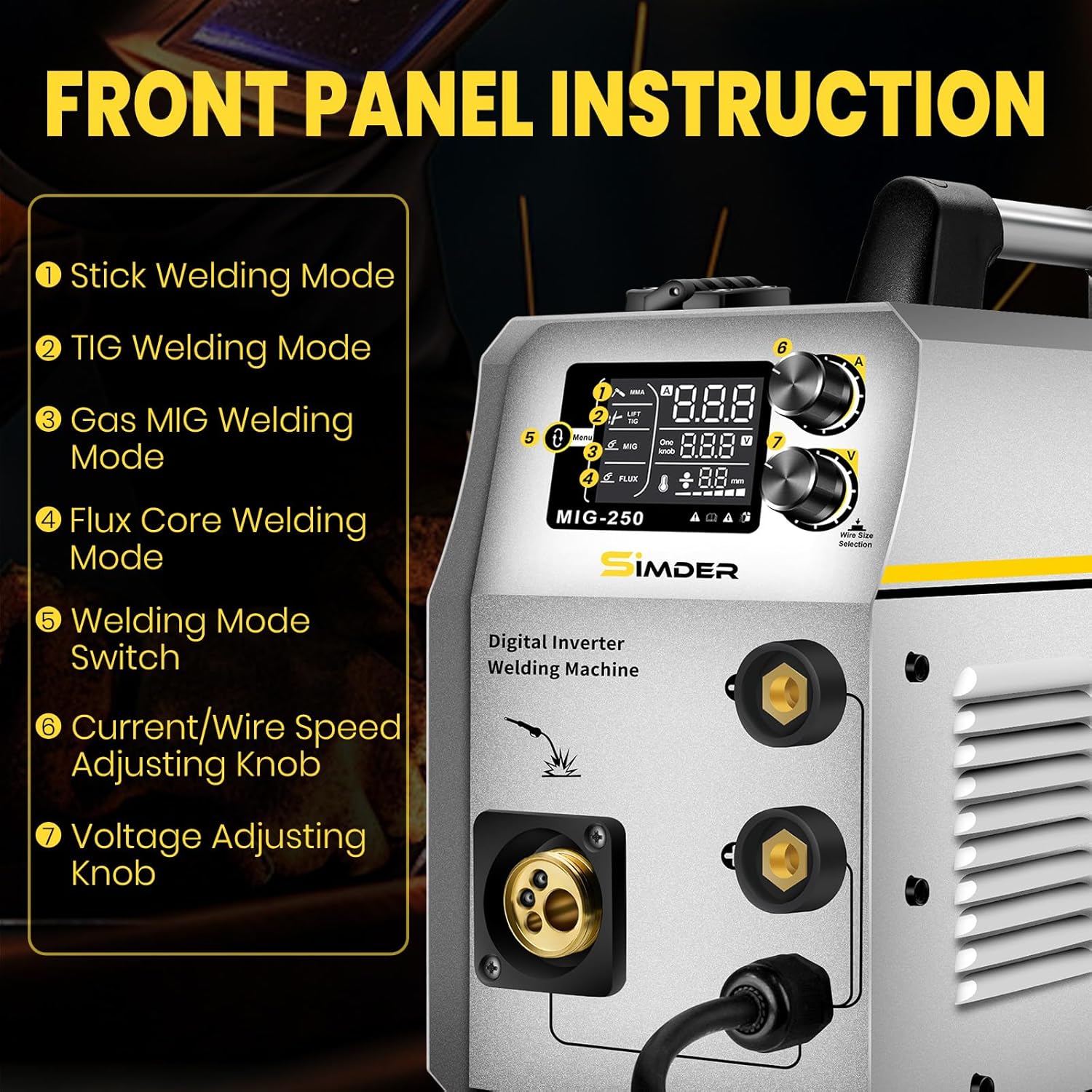
Figure 5: Front Panel Instruction and Controls.
The image highlights the front panel of the MIG250, detailing the functions of its controls: 1) Stick Welding Mode, 2) TIG Welding Mode, 3) Gas MIG Welding Mode, 4) Flux Core Welding Mode, 5) Welding Mode Switch, 6) Current/Wire Speed Adjusting Knob, and 7) Voltage Adjusting Knob.
Connection Diagrams:

Figure 6: MIG Welding Connection.
Diagram showing the connection points for MIG welding, including the MIG gun and ground clamp.

Figure 7: Flux Core Welding Connection.
Diagram showing the connection points for Flux Core welding, which typically uses the MIG gun and ground clamp without external gas.

Figure 8: Lift TIG Welding Connection.
Diagram showing the connection points for Lift TIG welding, including the TIG torch and ground clamp.

Figure 9: MMA/Stick Welding Connection.
Diagram showing the connection points for MMA/Stick welding, including the electrode holder and ground clamp.
4. Operating Instructions
Before operating, ensure all connections are secure and you are wearing appropriate personal protective equipment (PPE).
4.1 Selecting Welding Mode
Use the Welding Mode Switch on the front panel (refer to Figure 5) to select your desired welding process: MMA, Lift TIG, Flux MIG, or Gas MIG.
4.2 Adjusting Parameters
- Current/Wire Speed: Use the Current/Wire Speed Adjusting Knob to set the amperage for MMA/TIG or wire feed speed for MIG/Flux Core.
- Voltage: Use the Voltage Adjusting Knob to fine-tune the welding voltage. Note that the voltage knob may not display specific values but adjusts the arc characteristics.
Refer to welding charts for recommended settings based on material type and thickness. Always perform test welds on scrap material before beginning your project.
5. Maintenance
Regular maintenance ensures the longevity and optimal performance of your SSIMDER MIG250 welder.
- Cleaning: Periodically clean the internal components, especially the fan and air vents, to prevent dust and debris buildup. Use compressed air to clear any obstructions.
- Wire Feed System: Inspect the wire feed rollers and liner for wear or blockages. Clean or replace as needed to ensure smooth wire feeding.
- Connections: Check all electrical connections, including power cables, welding leads, and gas lines, for tightness and signs of damage.
- Cooling System: The high-performance fan motor provides essential cooling. Ensure the fan is unobstructed and functioning correctly to prevent overheating.
- Storage: Store the welder in a clean, dry environment, away from excessive dust, moisture, and extreme temperatures.

Figure 10: Multiple Protection Features.
This image illustrates the built-in safety features of the welder, including protection against over-voltage, over-current, and over-heating, which contribute to its durability and user safety.
6. Troubleshooting
This section addresses common issues you might encounter during operation.
| Problem | Possible Cause | Solution |
|---|---|---|
| No power/Machine does not turn on | Power cable disconnected, circuit breaker tripped, faulty power outlet. | Check power connections, reset circuit breaker, try a different outlet. |
| No arc/Poor arc stability | Improper ground clamp connection, incorrect settings, worn consumables, wire feed issue. | Ensure ground clamp is on clean metal, adjust current/voltage, replace contact tip/nozzle, check wire spool and feeder. |
| Wire not feeding | Wire tangled, feed roller tension incorrect, liner clogged, contact tip blocked. | Untangle wire, adjust roller tension, clean or replace liner, clear/replace contact tip. |
| Overheat protection activated | Extended use, blocked ventilation, high ambient temperature. | Allow machine to cool down, ensure clear airflow around the unit, reduce duty cycle. |
7. Specifications
| Attribute | Detail |
|---|---|
| Model Number | MIG250 (mig-250) |
| Manufacturer | S SIMDER |
| Item Weight | 10 pounds |
| Package Dimensions | 19.06 x 14.72 x 11.02 inches |
| Power Source | AC/DC |
| Input Voltage | 110V & 220V Dual Voltage |
| Applicable MIG Wire | 0.030" - 0.035" |
| Applicable Stick Electrodes | 7018, 6010, 6013 |
| Wire Spool Capacity | 2LBS / 10LBS Flux Core Wire / Solid Wire |

Figure 11: Detailed Electrical Specifications.
This image provides a table of detailed electrical specifications for the MIG250 model, including output current, voltage, and duty cycle information for various settings.
8. Warranty and Support
SSIMDER is committed to providing reliable tools and customer satisfaction. For any questions, technical assistance, or warranty claims, please contact the manufacturer directly. Contact information can typically be found on the product packaging or the official S SIMDER website.
The seller for this product is Simder. Please retain your proof of purchase for warranty purposes.