1. Introduction
This manual provides detailed instructions for the installation, operation, and maintenance of the ASUS TUF Gaming B660M-PLUS WiFi motherboard. This motherboard is designed to support 12th Generation Intel Core processors and DDR5 memory, offering a robust foundation for personal computer systems.
Please read this manual thoroughly before beginning the installation process to ensure proper setup and to prevent damage to components.
2. Safety Information
- Always disconnect the power cord from the wall outlet before touching any internal components.
- Wear an anti-static wrist strap or frequently touch a grounded metal object to discharge static electricity before handling components.
- Handle components by their edges to avoid touching sensitive circuits.
- Ensure proper ventilation within the computer case to prevent overheating.
- Keep the motherboard away from moisture and extreme temperatures.
- Refer to the CPU and memory manufacturer's guidelines for specific installation instructions.
3. Package Contents
Verify that your package contains the following items. If any item is damaged or missing, contact your retailer.
- ASUS TUF Gaming B660M-PLUS WiFi Motherboard
- I/O Shield (if not pre-mounted)
- SATA Data Cables
- M.2 Screw Package
- Wi-Fi Antenna
- Support DVD/USB Drive (containing drivers and utilities)
- User Manual and Quick Start Guide
4. Motherboard Layout
Familiarize yourself with the key components and connectors on the motherboard.

Figure 4.1: Top-down view of the ASUS TUF Gaming B660M-PLUS WiFi motherboard, showing the CPU socket, DIMM slots, PCIe slots, and heatsinks.
4.1 CPU Socket (LGA 1700)
The LGA 1700 socket supports 12th Generation Intel Core processors. Ensure the CPU is correctly oriented before installation.

Figure 4.2: Close-up of the LGA 1700 CPU socket on the motherboard, ready for processor installation.
4.2 DDR5 DIMM Slots
This motherboard features four DDR5 DIMM slots, supporting up to 128GB of system memory with speeds up to 6000MHz (OC).
4.3 PCIe Slots
Includes a PCIe 5.0 x16 slot for graphics cards and multiple PCIe 4.0 M.2 slots for high-speed storage.
4.4 SATA Ports
Four SATA 6Gb/s ports are available for connecting traditional hard drives and SSDs.
4.5 Rear I/O Panel
The rear I/O panel provides various connectivity options.

Figure 4.3: Detailed view of the rear I/O panel, showing USB ports, HDMI, DisplayPort, 2.5G Ethernet, Wi-Fi antenna connectors, and audio jacks.
- USB Ports: Multiple USB 2.0, USB 3.2 Gen 1, USB 3.2 Gen 2, and USB 3.2 Gen 2x2 Type-C ports.
- Video Outputs: HDMI, DisplayPort.
- Network: 2.5G Ethernet port, Wi-Fi 6 antenna connectors.
- Audio: Audio jacks for speakers, microphone, and line-in.
- S/PDIF Out: Optical S/PDIF digital audio output.
5. Setup and Installation
Follow these steps for proper installation of your motherboard and components.
5.1 Installing the CPU
- Open the CPU socket lever and lift the load plate.
- Carefully align the CPU with the socket, ensuring the triangular mark on the CPU matches the mark on the socket.
- Gently place the CPU into the socket without forcing it.
- Close the load plate and push down the lever until it locks into place.

Figure 5.1: Top-down view of the motherboard with a CPU installed in the LGA 1700 socket.
5.2 Installing RAM (DDR5)
- Open the clips at both ends of the DIMM slot.
- Align the notch on the DDR5 memory module with the key in the DIMM slot.
- Insert the memory module firmly into the slot until the clips snap into place.
- For optimal performance, install memory modules in the recommended dual-channel configuration (refer to the motherboard manual for specific slot pairing).
5.3 Installing Storage Devices
M.2 SSD Installation:
- Locate the M.2 slots on the motherboard. Some slots may have heatsinks that need to be removed first.
- Insert the M.2 SSD into the slot at a 30-degree angle.
- Push the SSD down and secure it with the provided M.2 screw or Q-Latch mechanism.
- If applicable, reattach the M.2 heatsink.
SATA Drive Installation:
- Connect one end of a SATA data cable to a SATA port on the motherboard.
- Connect the other end of the SATA data cable to your SATA hard drive or SSD.
- Connect a SATA power cable from your power supply to the drive.
5.4 Installing the Graphics Card
- Open the latch on the PCIe 5.0 x16 slot.
- Align your graphics card with the slot and press it down firmly until it clicks into place and the latch closes.
- Secure the graphics card to the computer case with screws.
- Connect any necessary PCIe power cables from your power supply to the graphics card.
5.5 Connecting Power Supply
- Connect the 24-pin ATX power connector from your power supply to the corresponding header on the motherboard.
- Connect the 8-pin and 4-pin (or 8-pin only, depending on your CPU power requirements) ATX 12V power connectors to the motherboard.
5.6 Connecting Front Panel Headers
Connect the cables from your computer case's front panel (power button, reset button, USB ports, audio jacks, LED indicators) to the corresponding headers on the motherboard. Refer to the motherboard diagram for exact locations.
5.7 Connecting Peripherals
Connect your monitor, keyboard, mouse, and other peripherals to the appropriate ports on the rear I/O panel.
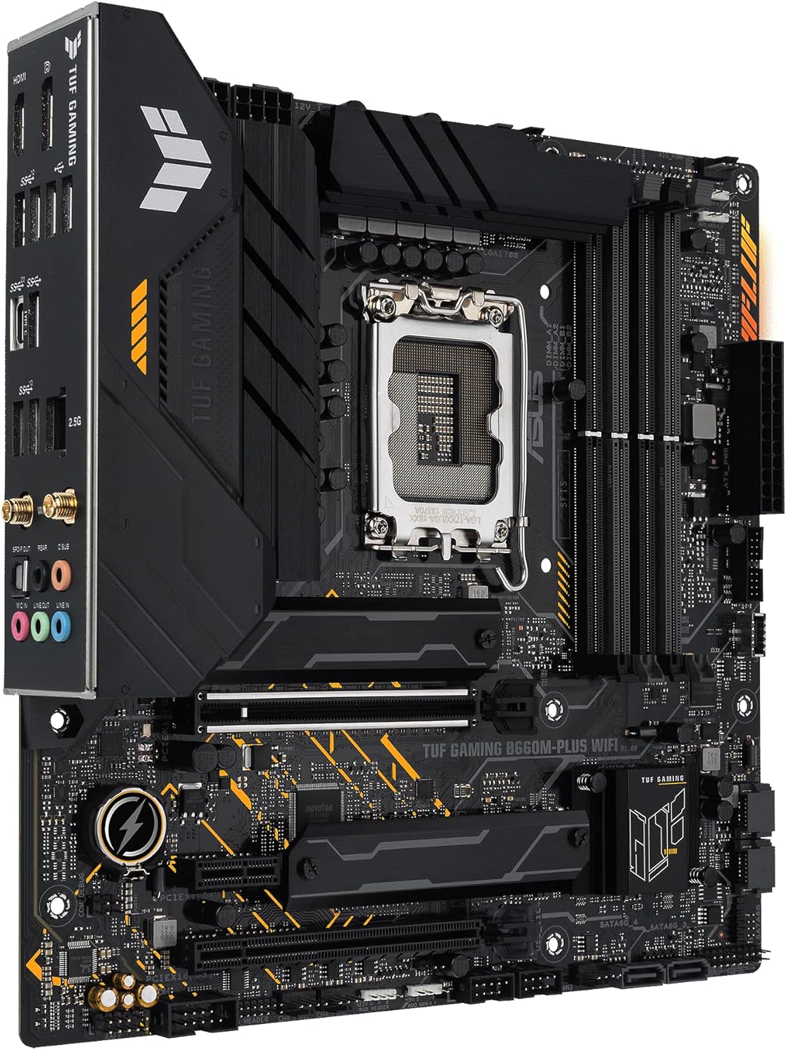
Figure 5.2: Angled view of the motherboard, highlighting the rear I/O panel and various connectors.
6. Operating Instructions
6.1 First Boot
- After assembling all components, connect the power cord to the power supply and turn on the power switch.
- Press the power button on your computer case.
- The system should power on and display the ASUS logo.
6.2 BIOS/UEFI Setup
To enter the BIOS/UEFI setup utility, press the Delete key or F2 key during the Power-On Self-Test (POST) process. Here you can configure system settings, boot order, and monitor hardware status.
6.3 Driver Installation
After installing your operating system, install the necessary drivers for the motherboard components. These can be found on the included support DVD/USB drive or downloaded from the official ASUS support website. The ASUS Armory Crate software can assist with driver and utility installation.
6.4 Software Utilities
The ASUS Armory Crate software provides tools for system monitoring, fan control (Fan Xpert 4), two-way AI noise cancellation, RGB lighting customization, and peripheral management.
7. Maintenance
- Cleaning: Regularly clean dust from inside your computer case using compressed air. Ensure the system is powered off and unplugged before cleaning.
- BIOS/UEFI Updates: Periodically check the ASUS support website for BIOS/UEFI updates. Updates can improve system stability, compatibility, and performance. Follow the instructions provided by ASUS carefully when updating the BIOS/UEFI.
- Driver Updates: Keep your drivers updated to ensure optimal performance and compatibility with new software and hardware.
8. Troubleshooting
If you encounter issues, consider the following common troubleshooting steps:
- No Power: Ensure all power cables (24-pin, 8-pin/4-pin CPU, PCIe for GPU) are securely connected. Check the power supply switch and wall outlet.
- No Display: Verify that the monitor is connected to the graphics card (or motherboard if using integrated graphics) and powered on. Reseat the graphics card and RAM modules.
- System Instability/Crashes: Check RAM installation and compatibility. Ensure CPU cooler is properly installed. Update drivers and BIOS/UEFI.
- Component Not Detected: Reseat the component (e.g., M.2 SSD, SATA drive, PCIe card). Check cable connections. Verify settings in BIOS/UEFI.
For more detailed troubleshooting or persistent issues, refer to the comprehensive manual on the ASUS support website or contact ASUS technical support.
9. Specifications
| Feature | Specification |
|---|---|
| Brand | ASUS |
| Model Name | TUF GAMING B660M-PLUS WIFI |
| CPU Socket | LGA 1700 |
| Compatible Processors | Intel LGA 1700 (12th Gen Intel Core) |
| Chipset Type | Intel B660 |
| RAM Memory Technology | DDR5 |
| Memory Clock Speed | Up to 6000 MHz (OC) |
| Max RAM Memory Size | 128 GB |
| Memory Slots Available | 4 |
| Graphics Card Interface | PCI Express 5.0 |
| Total PCIe Ports | 3 (1x PCIe 5.0 x16, others for M.2/expansion) |
| Total SATA Ports | 4 |
| USB Ports | Rear: USB 3.2 Gen 2x2 Type-C, USB 3.2 Gen 2, USB 3.2 Gen 1, USB 2.0. Front: USB 3.2 Gen 1 Type-C, USB 3.2 Gen 1, USB 2.0. |
| Ethernet | 2.5G Ethernet |
| Wireless Connectivity | Wi-Fi 6 |
| Video Outputs | HDMI, DisplayPort |
| Form Factor | Micro ATX |
| Model Number | 90MB1AZ0-M1EAY0 |
10. Warranty and Support
ASUS products are designed with quality and reliability in mind. For information regarding your product's warranty, please refer to the warranty card included in your package or visit the official ASUS website.
For technical support, driver downloads, BIOS updates, and further documentation, please visit the official ASUS support website:
When contacting support, please have your motherboard model name (TUF GAMING B660M-PLUS WIFI) and serial number ready.


