1. Introduction
The EVTSCAN Peakmeter PM8213C is a portable digital multimeter designed for various electrical measurements. This instrument offers stable performance, high precision, and low power consumption, making it a reliable tool for both professional and DIY users. Its compact appearance and comprehensive features ensure accurate readings for voltage, current, resistance, continuity, non-contact voltage (NCV), frequency, and duty cycle.
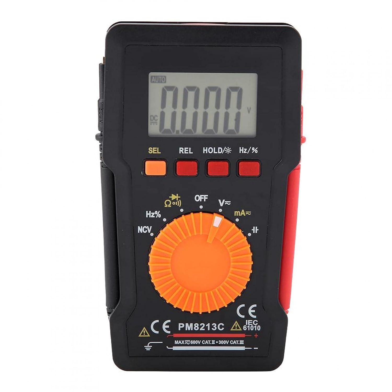
Figure 1: Front view of the EVTSCAN Peakmeter PM8213C Digital Multimeter.
2. Safety Information
To ensure safe operation and service of the meter, please read this manual carefully before use. Failure to observe safety warnings can result in serious injury or death. Always adhere to local and national safety codes.
- Do not exceed the maximum input limits for any function.
- Use caution when working with voltages above 30V AC RMS, 42V peak, or 60V DC. These voltages pose a shock hazard.
- Before measuring current, ensure the meter's test leads are connected to the correct input jacks and the function switch is set to the appropriate current range.
- Always disconnect the test leads from the circuit before changing the function switch position.
- Replace the battery immediately when the low battery indicator appears to ensure accurate readings.
- Do not operate the meter if it appears damaged or if the protective casing is removed.
- Keep hands and fingers behind the probe barriers during measurements.
3. Product Overview
3.1. Components
The PM8213C multimeter consists of the following main components:
- LCD Display: Shows measurement readings, units, and function indicators.
- Function Buttons: SEL (Select), REL (Relative), HOLD (Data Hold), Hz/% (Frequency/Duty Cycle).
- Rotary Switch: Used to select the desired measurement function (e.g., V~, V-, Ω, Continuity, NCV, Hz%, mA~, A~).
- Input Jacks: Terminals for connecting test leads (COM, VΩHz, mA, A).
- Test Leads: Red and black leads for connecting to the circuit under test.
- Protective Case: Provides protection for the meter.

Figure 2: Key features of the PM8213C Multimeter, including LCD screen and compact design.
3.2. Display Symbols
Familiarize yourself with the symbols that may appear on the LCD display:
- AUTO: Auto-ranging mode is active.
- DC/AC: Direct Current / Alternating Current.
- V: Volts (Voltage).
- Ω: Ohms (Resistance).
- Hz: Hertz (Frequency).
- %: Duty Cycle.
- NCV: Non-Contact Voltage detection.
- HOLD: Data Hold function is active.
- REL: Relative measurement mode.
- Battery Symbol: Indicates low battery power.
- OOL: Over-range indication.
4. Setup
4.1. Battery Installation
The PM8213C requires one CR2032 (3V) button cell battery for operation. The battery is typically not included in the package.
- Ensure the multimeter is turned OFF.
- Locate the battery compartment on the back of the meter.
- Use a suitable tool (e.g., a small screwdriver) to open the battery compartment cover.
- Insert the CR2032 battery, observing the correct polarity (+ and - markings).
- Replace the battery compartment cover and secure it.
4.2. Test Lead Connection
Connect the test leads to the appropriate input jacks before taking any measurements.
- Connect the black test lead to the COM (common) input jack.
- For most measurements (voltage, resistance, frequency, duty cycle, continuity), connect the red test lead to the VΩHz input jack.
- For current measurements (mA), connect the red test lead to the mA input jack.
- For higher current measurements (A), connect the red test lead to the A input jack (if available and distinct from mA). Note: The PM8213C typically uses a single current input for mA/A, check the dial for specific ranges.
5. Operating Instructions
5.1. Power On/Off
To turn the multimeter ON, rotate the function switch from the OFF position to any desired measurement function. To turn the multimeter OFF, rotate the function switch to the OFF position. The meter features an automatic power-off function after approximately 30 minutes of inactivity to conserve battery life.
5.2. Function Selection
Use the rotary switch to select the primary measurement function. For functions with multiple modes (e.g., AC/DC voltage, continuity/diode), press the SEL button to toggle between modes.
5.3. Measuring DC Voltage (V-)
- Connect the red test lead to the VΩHz jack and the black test lead to the COM jack.
- Set the rotary switch to the V- position.
- Connect the test leads in parallel to the DC voltage source or component you wish to measure.
- Read the voltage value on the LCD display.
5.4. Measuring AC Voltage (V~)
- Connect the red test lead to the VΩHz jack and the black test lead to the COM jack.
- Set the rotary switch to the V~ position.
- Connect the test leads in parallel to the AC voltage source or component.
- Read the voltage value on the LCD display.
5.5. Measuring Resistance (Ω)
- Ensure the circuit is de-energized before measuring resistance.
- Connect the red test lead to the VΩHz jack and the black test lead to the COM jack.
- Set the rotary switch to the Ω position.
- Connect the test leads across the component whose resistance you want to measure.
- Read the resistance value on the LCD display.
5.6. Continuity Test (Ω))))
- Ensure the circuit is de-energized.
- Connect the red test lead to the VΩHz jack and the black test lead to the COM jack.
- Set the rotary switch to the Continuity position (often shared with Resistance or Diode). Press SEL if needed to select continuity.
- Connect the test leads across the component or wire.
- If continuity exists (low resistance), the meter will emit an audible beep.
5.7. Non-Contact Voltage (NCV) Detection
- Set the rotary switch to the NCV position.
- Move the top edge of the multimeter close to the conductor suspected of having AC voltage.
- The meter will indicate the presence of AC voltage through an audible beep and/or visual indicator (e.g., LED).
5.8. Measuring Frequency (Hz) and Duty Cycle (%)
- Connect the red test lead to the VΩHz jack and the black test lead to the COM jack.
- Set the rotary switch to the Hz/% position.
- Connect the test leads in parallel to the signal source.
- Press the Hz/% button to toggle between frequency and duty cycle measurements.
- Read the value on the LCD display.
5.9. Measuring Current (mA~, A~)
- WARNING: Never connect the meter in parallel to a voltage source when measuring current. This will blow the fuse and can damage the meter.
- Ensure the circuit is de-energized.
- Connect the black test lead to the COM jack.
- For milliampere (mA) measurements, connect the red test lead to the mA jack. For ampere (A) measurements, connect the red test lead to the A jack (if separate).
- Set the rotary switch to the appropriate mA~ or A~ position.
- Open the circuit where you want to measure current and connect the meter in series with the load.
- Re-energize the circuit and read the current value on the LCD display.
6. Maintenance
6.1. Cleaning
Wipe the meter's case with a damp cloth and mild detergent. Do not use abrasives or solvents. Keep the input terminals free from dirt and moisture.
6.2. Battery Replacement
When the low battery indicator appears on the display, replace the CR2032 battery promptly to ensure accurate measurements.
- Turn the multimeter OFF and disconnect all test leads.
- Open the battery compartment cover on the back of the meter.
- Remove the old CR2032 battery.
- Insert a new CR2032 (3V) button cell battery, ensuring correct polarity.
- Securely close the battery compartment cover.
6.3. Fuse Replacement
If the current measurement function stops working, the fuse may need replacement. The fuse specification is F 400mA/250V.
- Turn the multimeter OFF and disconnect all test leads.
- Open the meter's casing (refer to the battery replacement section for access, or consult the full service manual if necessary).
- Locate the blown fuse.
- Carefully remove the old fuse and replace it with a new fuse of the exact same type and rating (F 400mA/250V).
- Reassemble the meter's casing securely.
7. Troubleshooting
If the meter does not function correctly, check the following points before seeking service:
- No display or faint display: Check battery installation and replace if necessary.
- Incorrect readings: Ensure test leads are correctly connected to the appropriate input jacks and the rotary switch is set to the correct function and range. Check battery level.
- Current measurement not working: Check and replace the fuse if blown. Ensure test leads are connected in series with the circuit.
- "OOL" displayed: The measured value exceeds the selected range. Switch to a higher range or ensure the input is within the meter's capabilities.
8. Specifications
| Altitude | Less than 2000 m |
| Operating Temperature | 0 ~ 40 °C |
| Operating Humidity | <80% RH (not considered at <10 °C) |
| Storage Temperature | -10 ~ 60 °C |
| Storage Humidity | <70% RH (remove batteries) |
| Temperature Coefficient | 0.1 precision/°C |
| Max Allowable Voltage (Input to Ground) | 600V DC or AC rms |
| Fuse Protection | F 400mA/250V |
| Sampling Rate | Approximately 3 times/second |
| Auto Power Off | Approximately 30 minutes |
| Display | Maximum 3999 counts |
| Over-range Display | "OOL" |
| Power Supply | CR2032 (3V) button cell battery |
| Weight | Approximately 120 - 142 g |
| Dimensions (L x W x H) | 127 x 70 x 12.5 mm (approx. 12.8 x 7.5 x 1.3 cm) |
8.1. DC Voltage (PM8213C)
| Range | Resolution | Accuracy |
|---|---|---|
| 4 V | 0.001 V | ±(0.1% + 3 digits) |
| 40 V | 0.01 V | ±(0.1% + 3 digits) |
| 400 V | 0.1 V | ±(0.1% + 3 digits) |
| 600 V | 1 V | ±(0.1% + 3 digits) |
8.2. Package Contents
- 1 x Digital Multimeter (PM8213C)
- 2 x Test Leads
- 1 x Protective Case
9. Warranty and Support
For warranty information or technical support, please contact the seller or manufacturer directly. Keep your purchase receipt as proof of purchase.