QIACHIP rx480e
QIACHIP 433MHz Wireless Remote Control Switch System User Manual
Model: RX480E-4WQB
1. Introduction
This manual provides detailed instructions for the QIACHIP 433MHz Wireless Remote Control Switch System, which includes multiple receiver modules and a versatile 10-in-1 remote control transmitter. This system is designed for various applications such as remote control switches, automotive anti-theft systems, home security, electric doors, remote control sockets, LED lighting, garage door openers, and more. Please read this manual thoroughly before installation and operation to ensure proper and safe use.
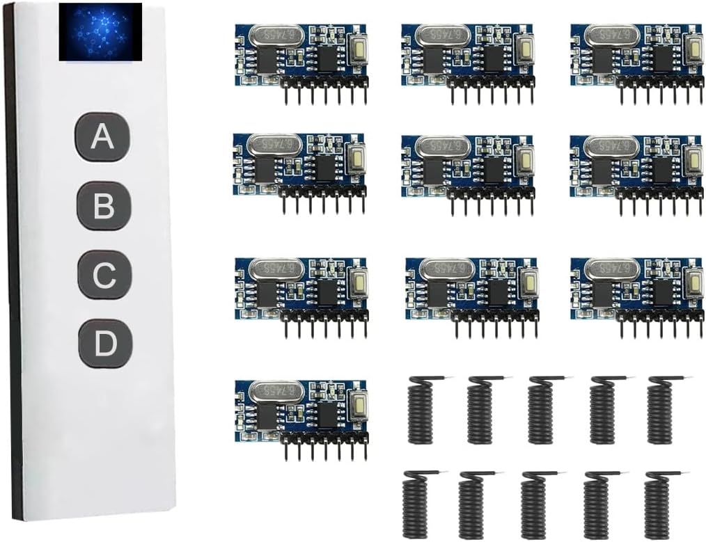
Figure 1.1: QIACHIP 433MHz Wireless Remote Control System Components
This image displays the complete QIACHIP 433MHz Wireless Remote Control System, featuring a sleek white 10-in-1 remote control on the left side, equipped with four control buttons (A, B, C, D) and a digital display. On the right, there are ten compact blue receiver modules, each with multiple pins for connection and a small coiled antenna, indicating their wireless reception capability.
2. Safety Information
For safe and optimal use of your QIACHIP Wireless Remote Control System, please adhere to the following guidelines:
- Battery Handling: Handle batteries with care. Ensure correct polarity when inserting. Do not mix old and new batteries, or different types of batteries. Dispose of used batteries responsibly according to local regulations.
- Interference: Avoid placing the device in close proximity to other wireless devices that operate on similar frequencies to prevent potential signal interference.
- Environmental Conditions: Store and operate the device in a dry, temperature-controlled environment. Avoid exposure to extreme temperatures, humidity, dust, or corrosive substances.
- Power Supply: Ensure the receiver module's working voltage (DC 3.3~5V) is strictly adhered to. Using an incorrect voltage can damage the device.
- Modifications: Do not attempt to modify or disassemble the components. Unauthorized modifications can void the warranty and pose safety risks.
3. Product Specifications
| Feature | Specification |
|---|---|
| Brand | QIACHIP |
| Model Number | RX480E-4WQB (Receiver Module) |
| Connectivity Technology | Radio Frequency (RF) |
| Operating Frequency | 433MHz |
| Receiver Module Working Voltage | DC 3.3V ~ 5V |
| Decoding Type | Learning Code 1527 |
| Output Channels | 4 Channel Output (D0, D1, D2, D3) |
| Remote Control Type | 10-in-1 Multi-Group Control Transmitter |
| Max Supported Devices (per 10-in-1 remote) | Up to 40 receivers (10 groups, 4 receivers per group) |
| Dimensions (Receiver Module) | Approx. 1.1 inch x 0.47 inch |
| Material | Plastic |
| Installation Method | Wireless |

Figure 3.1: Receiver Module Dimensions
This image provides a detailed view of the QIACHIP receiver module, highlighting its compact size with measurements of approximately 1.1 inches in length and 0.47 inches in width. The module features various electronic components and connection pins.
4. Components Overview
4.1. Receiver Module (RX480E-4WQB)
The receiver module is a compact 433MHz wireless receiver with a built-in 1527 decoding chip. It features 4 channel outputs (D0, D1, D2, D3) and a learning button for pairing with transmitters and setting working modes.

Figure 4.1: Receiver Module Pinout
This image shows a detailed view of the RX480E-4WQB receiver module, clearly labeling its seven connection pins: VT (Valid Transmit), D3, D2, D1, D0 (Data Outputs), +V (Power Supply), and GND (Ground). An antenna connection point is also visible, indicating where the coiled antenna should be attached for optimal signal reception.
4.2. 10-in-1 Remote Control Transmitter
This unique transmitter acts as ten independent 4-key remotes, allowing multi-group control without interference. It features a digital display and four buttons (A, B, C, D) for operation and ID switching.
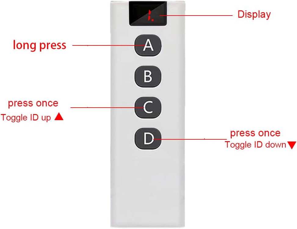
Figure 4.2: Remote Control Transmitter Layout
This image illustrates the layout of the 10-in-1 remote control transmitter. It features a digital display at the top, which shows the currently selected ID (0-9). Below the display are four large buttons labeled A, B, C, and D. The image indicates that button A is for "long press" functions, button C is used to "Toggle ID up", and button D is used to "Toggle ID down".
4.2.1. Remote Control Battery Installation
The remote control requires a 23A 12V battery (not included). To install or replace the battery:
- Locate the battery compartment cover on the back of the remote control.
- Slide the cover open.
- Insert a new 23A 12V battery, ensuring correct polarity (+ and -).
- Slide the cover back into place until it clicks securely.

Figure 4.3: Remote Control Battery Compartment
This image displays the underside of the remote control with its battery compartment cover removed, revealing the slot for a 23A 12V battery. A 23A 12V alkaline battery is shown separately, indicating the type of power source required for the remote.
5. Setup and Wiring
Before operating the system, ensure proper wiring of the receiver modules to your desired devices.
5.1. Receiver Module Wiring
The RX480E-4WQB receiver module has 7 pins for connection:
- +V: Power input (DC 3.3V ~ 5V)
- GND: Ground
- D0, D1, D2, D3: 4 Channel Outputs (These pins provide a signal when the corresponding button on the remote is pressed and the module is in Momentary or Toggle mode, or maintain state in Latched mode).
- VT: Valid Transmit (Indicates a valid signal reception).
Connect the +V and GND pins to a stable DC 3.3V-5V power source. The D0-D3 output pins can be connected to relays, LEDs, or other control circuits depending on your application. Ensure the coiled antenna is properly attached to the ANT pin for optimal range.

Figure 5.1: Example Wiring Diagram for Receiver Module
This image presents a circuit diagram demonstrating how to wire the RX480E receiver module. It shows connections for power (+V and GND) and how the D0, D1, D2, and D3 output pins can be connected to control four separate LEDs, illustrating a basic application of the module's 4-channel output capability.
6. Operating Instructions
6.1. Setting Receiver Module Working Modes
The receiver module supports three working modes: Momentary, Toggle, and Latched. These modes are set using the learning button on the receiver module.

Figure 6.1: Setting Receiver Working Modes
This image provides a close-up view of the receiver module, pointing out the small learning button. Text overlays explain how to set the module's working mode: pressing the button once sets "Momentary Mode", pressing it twice sets "Toggle Mode", and pressing it three times sets "Latched Mode".
- Momentary Mode (Press Once): The output is active only while the remote button is pressed. Release the button, and the output turns off.
- Toggle Mode (Press Twice): Press the remote button once to turn the output on. Press the same button again to turn the output off.
- Latched Mode (Press Three Times): Press one remote button (e.g., A) to turn an output on. Press another remote button (e.g., B) to turn that output off and potentially turn on another. In this mode, only one output can be active at a time.
To clear all learned codes from the receiver, press and hold the learning button for approximately 8 seconds until the indicator light flashes rapidly, then release. This will reset the receiver.
6.2. Pairing Remote Control with Receiver Modules
After setting the desired working mode, you need to pair the remote control with the receiver module.
- Ensure the receiver module is powered on.
- Briefly press the learning button on the receiver module (do not hold). The indicator light on the receiver will turn on, indicating it's in learning mode.
- Within 3 seconds, press any button (A, B, C, or D) on the 10-in-1 remote control. The receiver's indicator light will flash a few times and then turn off, indicating successful pairing.
- Test the remote control to ensure it operates the receiver as expected in the chosen mode.
6.3. Using the 10-in-1 Remote Control for Group Control
The 10-in-1 remote control allows you to control up to 40 receivers by organizing them into 10 independent groups (IDs 0-9). Each ID can control up to 4 receivers.
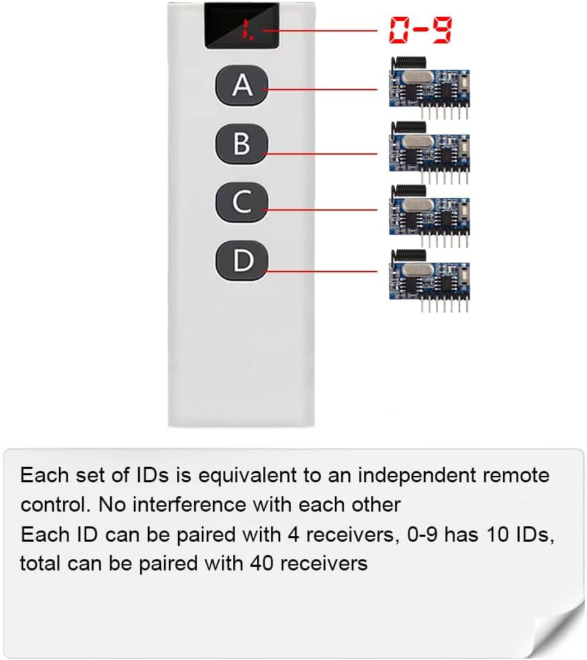
Figure 6.2: 10-in-1 Remote Control Grouping Capability
This image visually explains the group control functionality of the 10-in-1 remote. It shows the remote's digital display, which can cycle through IDs 0-9. For each ID, the remote can be paired with up to four receiver modules, allowing for a total of 40 individually controllable receivers across the ten groups. This setup ensures no interference between different groups.
6.3.1. Switching Between IDs (Groups)
To switch between the 10 available IDs (0-9) on the remote control:
- Increment ID: Press and hold the 'A' key without releasing, then press the 'C' key once. The digital display will increment to the next ID (e.g., from 0 to 1).
- Decrement ID: Press and hold the 'A' key without releasing, then press the 'D' key once. The digital display will decrement to the previous ID (e.g., from 1 to 0).
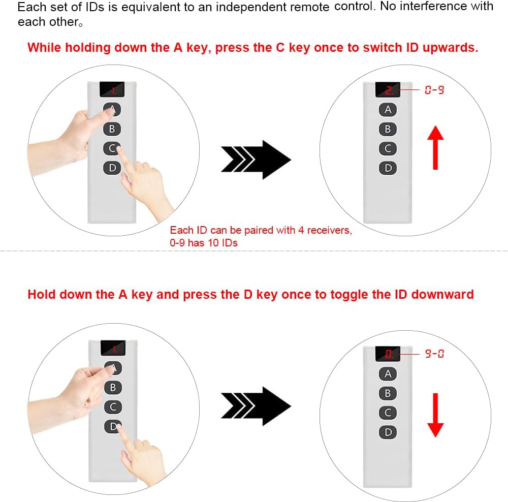
Figure 6.3: Remote Control ID Switching Method
This diagram illustrates the method for switching between different IDs on the 10-in-1 remote control. It shows that to increment the ID (from 0 to 9), you must hold down button A and then press button C. To decrement the ID (from 9 to 0), you must hold down button A and then press button D. The remote's display will show the current ID.
Each ID acts as an independent remote control. When you pair a receiver module, it learns the current ID of the remote. This allows you to control different sets of receivers without interference by simply switching the ID on your 10-in-1 remote.

Figure 6.4: Group Control Application Example
This image depicts an architectural floor plan of a house, illustrating the concept of "Group Control" with the QIACHIP system. It shows a hand holding the 10-in-1 remote control, with blue circles indicating various areas or devices within the house that can be controlled. The text states that one remote can control multiple receivers, up to 40, organized into 10 groups of IDs, with each group controlling 4 receivers, demonstrating the system's versatility for home automation.
7. Maintenance
The QIACHIP Wireless Remote Control System is designed for low maintenance. Follow these simple guidelines to ensure longevity:
- Cleaning: Use a soft, dry cloth to clean the remote control and receiver modules. Do not use abrasive cleaners, solvents, or immerse in water.
- Battery Replacement: Replace the remote control battery (23A 12V) when the signal weakens or the display becomes dim. Refer to Section 4.2.1 for battery installation.
- Storage: If storing the system for an extended period, remove the battery from the remote control to prevent leakage. Store components in a cool, dry place.
- Antenna: Ensure the receiver module's antenna is not bent or damaged, as this can affect signal reception range.
8. Troubleshooting
| Problem | Possible Cause | Solution |
|---|---|---|
| Remote control not responding / Receiver not activating. |
|
|
| Remote control battery drains quickly or gets hot. |
|
|
| Receiver module indicator light not behaving as expected during pairing. |
|
|
| Cannot switch IDs on 10-in-1 remote. |
|
|
9. Warranty and Support
QIACHIP products are manufactured with quality and reliability in mind. For specific warranty information, please refer to the product packaging or contact your retailer. If you encounter any issues or require technical assistance, please contact QIACHIP customer support through the official QIACHIP store on Amazon or their official website.
QIACHIP Store Link: Visit the QIACHIP Store on Amazon
Related Documents - rx480e
 |
QIACHIP RX480E-4 Receiver Module: Instructions, Specifications, and Operation Detailed instructions, specifications, and operational guide for the QIACHIP RX480E-4 433.92MHz superheterodyne wireless receiver module. Learn about clearing codes, learning modes (momentary, toggle, latching), pin-outs, applications, and wiring. |
 |
QIACHIP RX480E-868 Wireless Four Channel Decoding Receiver Module - Technical Specification Detailed technical specifications, features, applications, pin descriptions, and operating modes for the QIACHIP RX480E-868 FSK RF remote control receiver module. |
 |
QIACHIP 12V 4-Channel Wireless Receiver Instruction Manual and Technical Specifications Detailed instructions and technical specifications for the QIACHIP 12V 4-Channel Wireless Receiver, covering wiring diagrams, operating modes (Momentary, Toggle, Latching), and setup procedures for wireless remote control applications. |
 |
2 Channel 433MHz RF Receiver Module with Learning Code - Product Manual This product manual provides detailed instructions for the 2-channel 433MHz RF receiver module. It covers specifications, programming procedures for momentary, latched, and toggle modes, remote control setup, and wiring diagrams. Manufactured by Shenzhen Scimagic Development Technology Co.,Ltd. |
 |
433MHz Wireless Remote Control Light Switch User Manual Comprehensive user manual for the 433MHz Wireless Remote Control Light Switch. Includes technical specifications, wiring instructions, pairing procedures, countdown timer settings, and safety guidelines. |
 |
QA-R-011 Light Control Module Specification Specifications and operating instructions for the QA-R-011 Light Control Module, a wireless RF remote control switch for LED lighting with momentary, toggle, latching, and time delay modes. |
Ask a question about this manual
Ask about setup, troubleshooting, compatibility, parts, safety, or missing instructions. Manuals+ will review the question and use this page’s manual context to help answer it.