1. Introduction
The DORHEA Buck Boost Converter is a versatile adjustable voltage regulator designed to convert an input DC voltage (6V-36V) to a stable output DC voltage (0.6V-36V). It features both step-up and step-down capabilities, constant current functionality, and various protection mechanisms, making it suitable for a wide range of applications including power supply, battery charging, and LED driving.
2. Safety Information
- Always ensure the input voltage is within the specified range (DC 6V-36V). Exceeding this range can damage the device.
- Observe correct polarity when connecting input and output terminals. Reverse polarity protection is included, but incorrect wiring can still lead to issues.
- Do not exceed the maximum output current of 5A or output power of 80W to prevent overheating and damage.
- Ensure proper ventilation, especially when operating at higher power levels, as the device may generate heat.
- Keep the device away from moisture, dust, and extreme temperatures.
- Disconnect power before making any wiring changes or adjustments.
3. Product Features
- Wide Input Voltage Range: DC 6V-36V.
- Adjustable Output Voltage: DC 0.6V-36V, with 0.01V resolution.
- Adjustable Output Current: 0-5A, with 0.001A resolution.
- Maximum Output Power: 80W.
- Constant Current (CC) Function: Ideal for charging rechargeable batteries (0.6V-36V).
- Multi-functional Display: Shows input/output voltage (V), current (A), temperature (T), power (W), electric capacity (AH), electric quantity (WH), and running time.
- Graphical Display: Voltage and current curves interface.
- Customizable Display: Flip/rotate display, change background/parameter colors, switch day/night display mode.
- Memory Function: Saves voltage and current settings after power down.
- Comprehensive Protection: Over-voltage protection (OVP), over-current protection (OCP), over-power protection (OPP), low-voltage protection (LVP), over-temperature protection (OTP), reverse protection, and short circuit protection.
4. Specifications
| Parameter | Value |
|---|---|
| Input Voltage Range | DC 6.0V-36V |
| Output Voltage Range | DC 0.6V-36V |
| Output Current | 0-5.0A |
| Output Power | 80W (Max) |
| Input Current Limit | 6A (Max) |
| Voltage Resolution | 0.01V |
| Current Resolution | 0.001A |
| Voltage Precision | ±0.3% + 1 byte |
| Current Precision | ±0.4% + 3 bytes |
| Capacity Measurement | 0-999999AH |
| Energy Measurement | 0-999999WH |
| Time Measurement | 0-1000 Hours |
| Mounting Type | Portable (Panel Mount Design) |
| Dimensions (Approx.) | 79mm x 43mm x 53mm (L x W x H) |
5. Package Contents
- 2 x DORHEA DC 6.0V-36V to DC 0.6-36V 5A Buck Boost Converter Modules
6. Setup
6.1 Physical Overview

Image 1: Front view of the DORHEA Buck Boost Converter. This image shows the main display screen, the rotary encoder knob for adjustments, and the ON/OFF button. The display is active, showing output voltage (05.00V), current (0.121A), and power (00.60W).

Image 2: Top-down view of the converter's internal components. This image highlights the cooling fan, inductors, capacitors, and the screw terminals for input and output connections. The fan is centrally located for heat dissipation.
6.2 Dimensions and Mounting
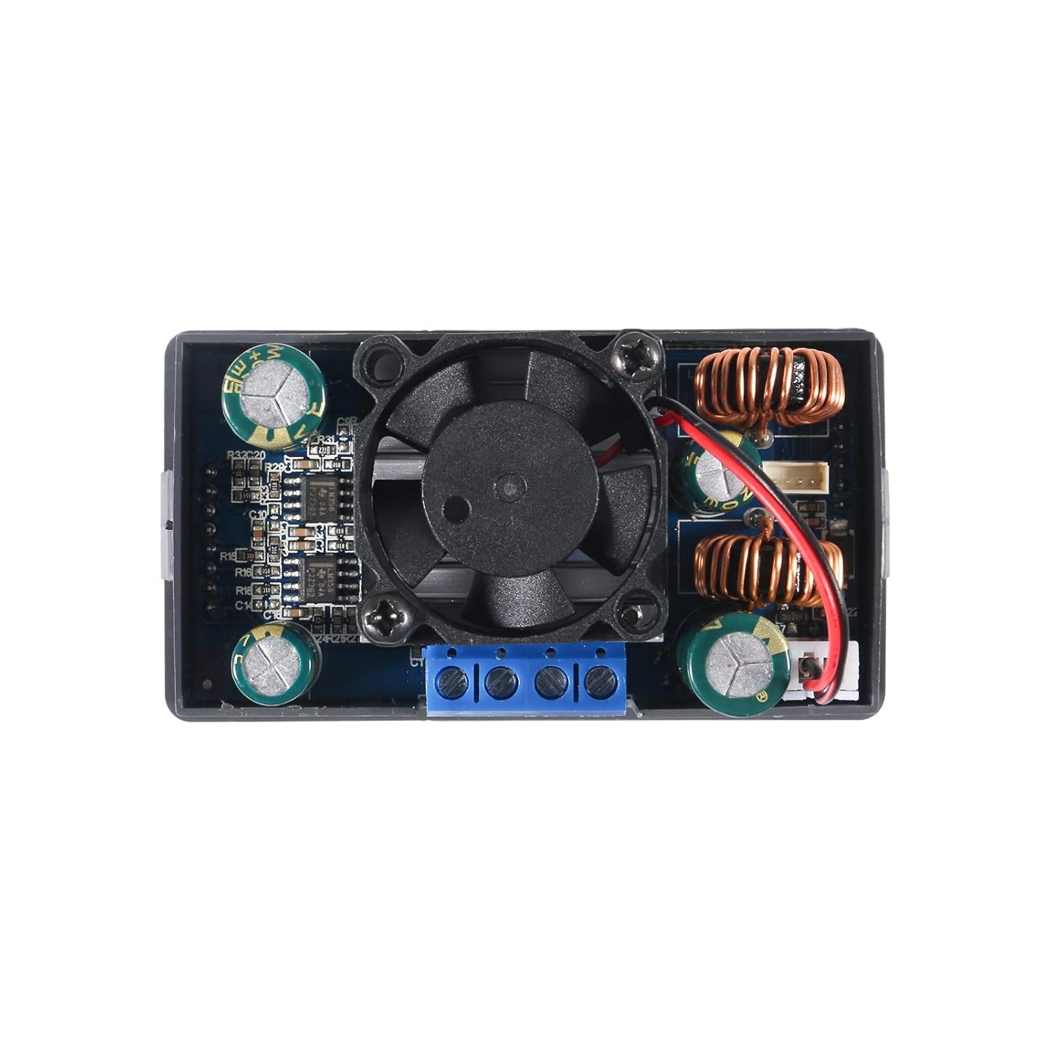
Image 3: Dimensional drawing of the converter. This image provides key measurements for the device, including a length of 79mm (3.11in), width of 43mm (1.69in), and height of 53mm (2.09in). These dimensions are crucial for enclosure design and mounting.
The converter is designed for panel mounting. The cutout dimensions required for installation are approximately 72mm x 40mm, with a 12mm x 2.5mm notch centered on each narrow side for securing the unit.
6.3 Wiring Connections
Identify the input and output terminals on the back of the module. These are typically labeled:
- VIN+: Positive input voltage
- VIN-: Negative input voltage (Ground)
- OUT+: Positive output voltage
- OUT-: Negative output voltage (Ground)
Use appropriate gauge wires for your input power source and load. Ensure all connections are secure within the screw terminals. For stranded wires, it is recommended to twist and tin the ends with solder for a more reliable connection.

Image 4: Rear view of the converter, highlighting the screw terminals. The labels VIN+, VIN-, OUT+, and OUT- are visible, indicating where to connect the input power source and the load.
7. Operating Instructions
7.1 Power On/Off
Once wired, apply input power. The unit will typically power on automatically. Use the dedicated ON/OFF button on the front panel to toggle the output power.
7.2 Adjusting Voltage and Current
The rotary encoder knob is used to adjust parameters. Press the knob to select a parameter (e.g., voltage or current). Rotate the knob to change the value. You may need to cycle through digit positions to set precise values. Press the knob again to confirm or move to the next digit/parameter.
7.3 Display Pages and Settings
The converter features multiple display pages that can be cycled through to view various operational parameters:
- Input/Output Voltage (V)
- Current (A)
- Temperature (T)
- Power (W)
- Electric Capacity (AH)
- Electric Quantity (WH)
- Running Time
- Voltage and Current Graphs
- System Parameter Settings
Refer to the on-screen menu for navigation and customization options, which may include flipping or rotating the display, changing background and parameter colors, and switching between day and night display modes.
7.4 Constant Current (CC) Function
The constant current function allows the module to maintain a set output current regardless of load changes (within its operational limits). This is particularly useful for charging batteries or driving LEDs that require a stable current. To use this function, set the desired current limit. The module will then regulate the output current to this value.
7.5 Protection Functions
The module includes several built-in protection features:
- Over-Voltage Protection (OVP): Shuts down output if voltage exceeds a set limit.
- Over-Current Protection (OCP): Limits or shuts down output if current exceeds a set limit.
- Over-Power Protection (OPP): Limits or shuts down output if power exceeds a set limit.
- Low-Voltage Protection (LVP): Shuts down output if input voltage drops below a set threshold.
- Over-Temperature Protection (OTP): Shuts down output if the module's temperature becomes too high.
- Reverse Protection: Protects against damage from incorrect input polarity.
- Short Circuit Protection: Protects against damage from output short circuits.
These protections are designed to safeguard both the converter and the connected load. If a protection is triggered, the display will typically indicate the fault.
8. Maintenance
- Cleaning: Keep the module clean and free from dust. Use a soft, dry cloth for cleaning. Avoid using liquids or solvents.
- Heat Sink/Fan: Periodically check the cooling fan for obstructions and ensure it operates freely. Ensure the heat sink is securely attached to the components for effective heat dissipation. If the heat sink or fan circuit board appears loose, it can be secured with a small amount of non-conductive adhesive.
- Terminal Connections: Regularly inspect screw terminal connections to ensure they remain tight and secure. Loose connections can lead to intermittent operation or overheating.
9. Troubleshooting
- No Output Voltage:
- Check input power supply and connections.
- Ensure the ON/OFF button has been pressed to enable output.
- Verify that no protection functions (e.g., OVP, OCP, LVP) have been triggered.
- Inaccurate Output Voltage/Current:
- Use a calibrated external multimeter to verify the output.
- Ensure the load is not drawing more current than the set limit or the module's maximum capacity.
- If significant discrepancies persist, the unit may require calibration or be faulty.
- Module Overheating:
- Reduce the load or ensure it is within the 80W power limit.
- Check for proper ventilation around the module.
- Ensure the cooling fan is operating correctly and not obstructed.
- Intermittent Operation or Display Issues:
- Check all wiring connections for looseness.
- Inspect the internal circuit board, especially the heat sink/fan board, for any loose connections or components. Gently re-seat or secure if necessary (e.g., with a small dab of hot glue on non-critical areas).
10. Warranty and Support
For warranty information or technical support, please refer to the product listing on the retailer's website or contact DORHEA directly through their official channels. You can often find support contact information on the brand's store page, such as the DORHEA Store on Amazon.