1. Introduction
This manual provides instructions for the safe and efficient use of the Rakstore XY-HXC DC-DC 5A Step Down Buck Power Module. This module is designed for voltage step-down, constant current/constant voltage (CC/CV) applications, LED driving, and lithium battery charging.
2. Safety Information
- Always observe the specified input and output voltage limits to prevent damage to the module or connected devices.
- Ensure correct input and output polarity before applying power. Incorrect polarity can cause irreversible damage.
- Avoid short circuits on the output terminals.
- Do not exceed the recommended output current (4.5A) or power (50W) for continuous operation to prevent overheating.
- Operate the module within the specified working temperature range (-40°C to +85°C).
- Handle the module with care to prevent electrostatic discharge, which can damage sensitive electronic components.
3. Product Overview
The XY-HXC module is a compact DC-DC step-down converter with an integrated digital display for voltage and current monitoring. It features adjustable output voltage and current, making it suitable for various power supply applications.
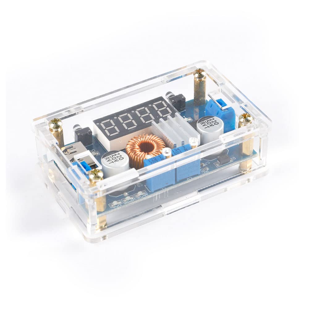
Figure 1: Assembled Rakstore XY-HXC DC-DC Buck Power Module. This image displays the fully assembled XY-HXC DC-DC buck converter module, enclosed in a transparent protective shell. The digital display, input/output terminals, and adjustment potentiometers are visible.
4. Specifications
| Parameter | Value |
|---|---|
| Input Voltage | 5-36V DC |
| Output Voltage | 1.25-32V DC (Continuously Adjustable) |
| Output Current | Up to 5A (Recommended within 4.5A) |
| Output Power | Up to 75W (Recommended within 50W) |
| Working Temperature | -40°C to +85°C |
| Working Frequency | 180KHz |
| Conversion Efficiency | Up to 96% |
| Short Circuit Protection | Yes |
| Over Temperature Protection | Yes (Automatic Output Shutdown) |
| Input Reverse Connection Protection | None (External diode required if needed) |
| Dimensions | 68.2 x 38.8 x 15 mm |
5. Setup and Assembly
The module may come unassembled with a protective shell. Follow these steps for assembly and initial setup.

Figure 2: Unassembled XY-HXC Module Components. This image shows the individual components of the XY-HXC module before assembly. It includes the main circuit board, the laser-cut clear acrylic shell pieces, and the necessary screws and standoffs for construction.
- Assemble the acrylic shell around the PCB using the provided screws and standoffs. Ensure all components are securely fitted.
- Identify the input terminals (IN+ / IN-) and output terminals (OUT+ / OUT-). These are typically marked on the PCB.
- Connect your DC input power source (5-36V) to the IN+ and IN- terminals, carefully observing polarity.
- Connect your load (e.g., LED, battery to be charged, or other device) to the OUT+ and OUT- terminals.
- Note: If the input voltage is 5V, the digital display may not show an accurate reading. In this case, use an external voltmeter to measure and adjust the output voltage. The display functions normally with input voltages greater than 6.5V.
6. Operating Instructions
The module features two potentiometers for adjustment and a digital display for monitoring.

Figure 3: Top View of Assembled Module. A top-down view of the assembled XY-HXC module, clearly showing the four-digit LED display, the input and output screw terminals, and the two blue potentiometers used for voltage and current adjustment.
6.1. Voltage Adjustment
To adjust the output voltage, rotate the potentiometer labeled "V-ADJ" (Voltage Adjust). Turning it clockwise will increase the voltage, and counter-clockwise will decrease it. Monitor the output voltage on the digital display or with an external voltmeter for precise adjustment.
6.2. Current Adjustment (Constant Current Mode)
To set the constant current limit, rotate the potentiometer labeled "I-ADJ" (Current Adjust). This feature is typically used for applications like battery charging or driving LEDs that require a constant current.
- Connect a multimeter in series with the output to measure the current, or connect a load that will draw the desired current.
- Adjust the "I-ADJ" potentiometer until the desired current limit is reached.
- Note: The module operates in constant voltage (CV) mode until the connected load attempts to draw more current than the set limit, at which point it automatically switches to constant current (CC) mode.
6.3. Digital Display Modes
The digital display can show either the input voltage, output voltage, or output current. Use the small button located next to the display to cycle through these measurement modes.
7. Maintenance
- Keep the module clean and free from dust and debris.
- Ensure adequate ventilation, especially when operating the module at higher power levels or in enclosed spaces.
- Periodically check all electrical connections for tightness and ensure they are secure.
- Avoid exposing the module to moisture, corrosive environments, or extreme temperatures outside its specified operating range.
8. Troubleshooting
8.1. No Output Voltage
- Check the input power supply connection and verify that the input voltage is within the 5-36V range.
- Confirm that the input polarity is correct (IN+ to positive, IN- to negative).
- Ensure the module is not in over-temperature protection; allow it to cool down if it has been operating under heavy load.
- Check for any short circuits on the output terminals or connected load.
8.2. Output Voltage Cannot Be Adjusted
- Ensure the input voltage is stable and within the specified range (5-36V).
- Verify that the "V-ADJ" potentiometer is functioning correctly and not damaged.
8.3. Output Current Cannot Be Adjusted
- Ensure a load is connected that attempts to draw current. The module will not enter constant current mode without a load.
- Verify that the "I-ADJ" potentiometer is functioning correctly.
- Remember that the module will only enter constant current mode if the load demands more current than the set limit.
9. Dimensions
The physical dimensions of the module are important for integration into projects and enclosures.

Figure 4: XY-HXC Module Dimensions. This image illustrates the physical dimensions of the XY-HXC module, indicating a length of approximately 78-79mm and a width of 48mm, including the protective shell.
10. Warranty and Support
For warranty information or technical support regarding your Rakstore XY-HXC DC-DC 5A Step Down Buck Power Module, please refer to the documentation provided by your seller or contact the point of purchase. Keep your purchase receipt for warranty claims.