1. Introduction
This manual provides detailed instructions for the safe and effective operation of the Syrolink COMPTYCO AUA-G510B Optical Fiber Power Meter. This device is designed for measuring optical power in fiber optic networks, featuring a wide measurement range, multiple wavelengths, a Visual Fault Locator (VFL), and an integrated LED light. Please read this manual thoroughly before using the product to ensure proper functionality and to prevent damage.
2. Safety Information
Observe the following safety precautions to prevent injury and damage to the device:
- Do not expose the device to extreme temperatures, humidity, or direct sunlight.
- Avoid direct eye exposure to the VFL laser light. The laser output can cause eye damage.
- Use only the specified battery type (AA). Ensure correct polarity when inserting batteries.
- Do not attempt to disassemble or modify the device. Refer all servicing to qualified personnel.
- Keep the optical ports clean to ensure accurate measurements.
3. Package Contents
Verify that all items are present in the package:
- COMPTYCO AUA-G510B Optical Fiber Power Meter (Host)
- SC/FC Adapter
- Certificate of Approval
- Instruction Manual (this document)
- Color Box Packaging
- Note: AA batteries are not included and must be purchased separately.
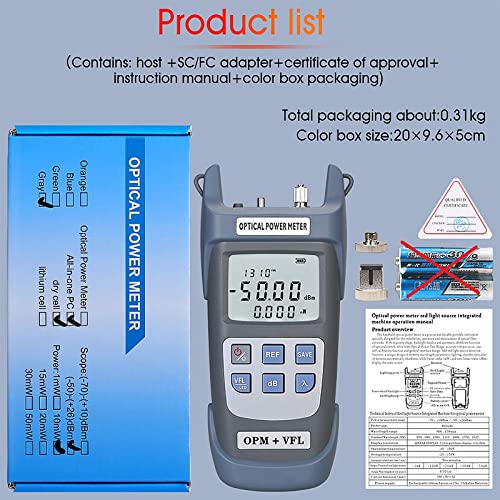
Figure 3.1: Contents of the product package, including the power meter, adapters, and documentation.
4. Product Overview
The AUA-G510B is a handheld optical power meter with integrated VFL and LED light. It features a clear LCD display and intuitive button controls.

Figure 4.1: Front view of the AUA-G510B Optical Fiber Power Meter.
4.1 Key Features
- Measurement Range: -50 to +26 dBm
- Wavelengths: 850nm, 980nm, 1300nm, 1310nm, 1490nm, 1550nm, 1625nm
- Visual Fault Locator (VFL): 10mW output power
- Integrated LED Light for dark environments
- Automatic Shutdown after 10 minutes of inactivity
- 500 groups of data storage
- Universal 2.5mm interface for SC/FC/ST connectors (LC optional)
4.2 Device Layout and Dimensions
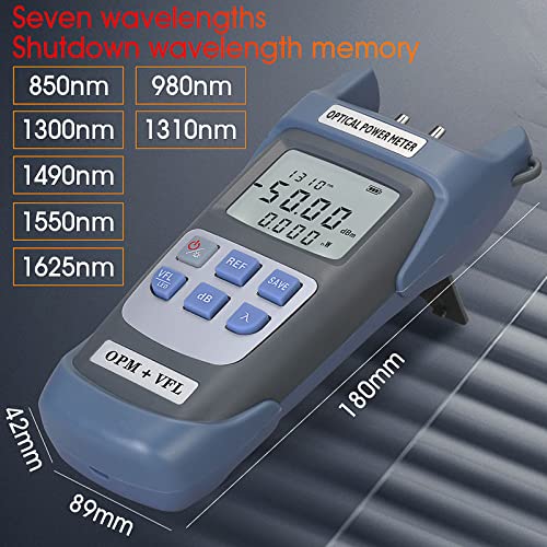
Figure 4.2: Device dimensions and supported wavelengths.
The device measures approximately 180mm in length, 89mm in width, and 42mm in height. It supports seven wavelengths for optical power measurement: 850nm, 980nm, 1300nm, 1310nm, 1490nm, 1550nm, and 1625nm.
4.3 Universal Interface
The AUA-G510B features a 2.5mm universal interface compatible with SC, FC, and ST optical fiber connectors. An LC adapter may be used for LC connectors (sold separately).
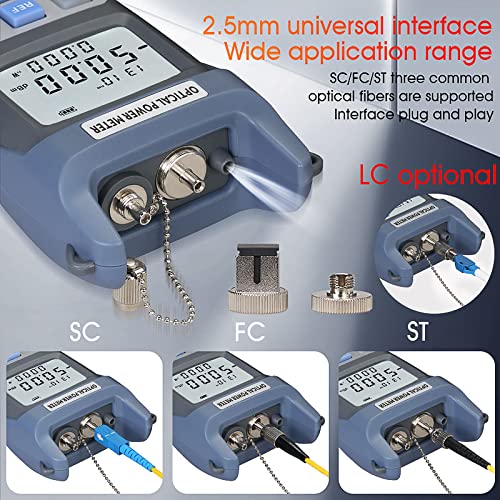
Figure 4.3: Universal interface for various fiber optic connectors.
5. Setup
5.1 Battery Installation
The device operates on AA batteries (not included). To install batteries:
- Locate the battery compartment on the back of the device.
- Open the battery cover.
- Insert two AA batteries, ensuring correct polarity (+/-).
- Close the battery cover securely.

Figure 5.1: Battery compartment location and battery type. This image also illustrates the device's control buttons.
6. Operating Instructions
6.1 Power On/Off
- To power on: Press the Power button briefly.
- To power off: Press and hold the Power button for approximately 2 seconds. The device also features an automatic shutdown function after 10 minutes of inactivity.
6.2 Wavelength Selection
To select the desired measurement wavelength:
- Press the λ (Wavelength) button repeatedly to cycle through the available wavelengths (850nm, 980nm, 1300nm, 1310nm, 1490nm, 1550nm, 1625nm). The selected wavelength will be displayed on the screen.
6.3 Optical Power Measurement
- Ensure the device is powered on and the correct wavelength is selected.
- Clean the optical connector of the fiber to be tested and the power meter's optical port.
- Connect the fiber optic cable to the optical power input port.
- The measured optical power will be displayed on the LCD screen in dBm or mW.
- Press the dB button to switch between absolute power (dBm) and relative power (dB).
6.4 Setting Reference Value (dB)
To set a reference value for relative power measurements:
- Connect a known reference power source to the meter.
- Press the REF button. The current power reading will be set as the 0dB reference, and subsequent measurements will be displayed as relative loss/gain in dB.
- To clear the reference, press the REF button again.
6.5 Data Storage
The device can store up to 500 groups of measurement data.
- To save a measurement: Press the SAVE button. The current reading will be stored.
- To view stored data: The manual does not specify a direct viewing method on the device. Data is typically retrieved via software or by cycling through saved records if a dedicated button exists (not apparent from images).
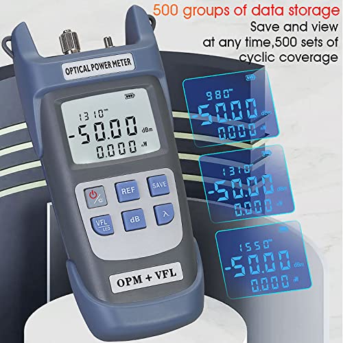
Figure 6.1: Data storage capability of the device.
6.6 Visual Fault Locator (VFL)
The integrated 10mW VFL is used to locate breaks, bends, and poor connections in fiber optic cables.
- To activate VFL: Press the VFL/LED button briefly. A red laser light will emit from the VFL port.
- To deactivate VFL: Press the VFL/LED button again.
- WARNING: Avoid direct eye exposure to the VFL laser light.
6.7 LED Light Function
The device includes an LED light for illuminating work areas.
- To activate LED light: Press and hold the VFL/LED button for approximately 2 seconds.
- To deactivate LED light: Press and hold the VFL/LED button again for approximately 2 seconds.
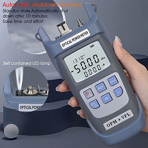
Figure 6.2: Integrated LED light and automatic shutdown feature.
6.8 User Self-Service Calibration
The device supports user self-service calibration. This function allows for fine-tuning the measurement accuracy.
- To enter calibration function: In the shutdown state, press the Power button and the λ (Wavelength) button simultaneously for 2 seconds. The calibration interface will appear after booting.
- Use the REF button to increase the value by 0.1dB.
- Use the dB button to decrease the value by 0.1dB.
- Refer to the on-screen prompts during calibration for specific adjustments.
7. Maintenance
7.1 Cleaning Optical Ports
Dust and debris on the optical ports can significantly affect measurement accuracy. Always ensure ports are clean before use.
- Use a lint-free optical cleaning swab or compressed air to gently clean the optical input port and VFL output port.
- Avoid touching the optical surfaces with bare hands.
7.2 Storage
- When not in use, store the device in a dry, dust-free environment, preferably in its original packaging or a protective case.
- Remove batteries if the device will not be used for an extended period to prevent leakage.
8. Troubleshooting
- Device does not power on:
- Check if batteries are installed correctly with proper polarity.
- Replace with fresh AA batteries.
- Inaccurate power measurement:
- Ensure optical ports and fiber connectors are clean.
- Verify that the correct wavelength is selected on the device, matching the light source.
- Check if the fiber cable is properly connected and not damaged.
- Perform user self-service calibration if necessary.
- VFL light is dim or not working:
- Ensure the VFL port is clean.
- Check battery level.
- The VFL ceramic core may be replaceable if damaged (refer to Figure 8.1).

Figure 8.1: VFL port with replaceable ceramic core.
9. Specifications
| Feature | Specification |
|---|---|
| Model Number | AUA-G510B |
| Measurement Range | -50 ~ +26 dBm |
| Wavelengths | 850nm, 980nm, 1300nm, 1310nm, 1490nm, 1550nm, 1625nm |
| VFL Laser Power | 10mW |
| Connector Type | Universal 2.5mm (SC/FC/ST compatible) |
| Battery Type | AA (2 units) |
| Item Weight | 280 g |
| Product Dimensions (LxWxH) | 19.8 x 9.8 x 5 cm |
| Data Storage | 500 groups |
| Automatic Shutdown | After 10 minutes of inactivity |
10. Warranty and Support
For warranty information and technical support, please contact your retailer or the manufacturer, Syrolink. Keep your purchase receipt as proof of purchase.
Manufacturer/Importer: Syrolink Networks Pvt Ltd, 3/120, Block No 3, Khichripur Colony, Delhi 110091, India. Contact: 8285865659